20 cHAPTER 2: Cooling System Design and Temperature Control
Model 336 Temperature Controller
2.4.7 Lead Soldering
When you solder additional wire to short sensor leads, be careful not to overheat the
sensor. A thermal anchor such as a metal wire clamp or alligator clip will anchor the
leads and protect the sensor. Leads should be tinned before bonding to reduce the
time that heat is applied to the sensor lead. Clean the solder flux after soldering to
prevent corrosion or outgassing in vacuum .
2.4.8 Thermal
Anchoring Leads
Sensor leads can be a significant source of error if they are not properly anchored.
Heat will transfer down even small leads and alter the sensor reading. The goal of
thermal anchoring is to cool the leads to a temperature as close to the sensor as possi-
ble. This can be accomplished by putting a significant length of lead wire in thermal
contact with every cooled surface between room temperature and the sensor. You
can adhere lead wires to cold surfaces with varnish over a thin electrical insulator like
cigarette paper. They can also be wound onto a bobbin that is firmly attached to the
cold surface. Some sensor packages include a thermal anchor bobbin and wrapped
lead wires to simplify thermal anchoring.
2.4.9 Thermal
Radiation
Thermal (black body) radiation is one of the ways heat is transferred. Warm surfaces
radiate heat to cold surfaces even through a vacuum. The difference in temperature
between the surfaces is one thing that determines how much heat is transferred.
Thermal radiation causes thermal gradients and reduces measurement accuracy.
Many cooling systems include a radiation shield. The purpose of the shield is to sur-
round the sample stage, sample, and sensor with a surface that is at or near their tem-
perature to minimize radiation. The shield is exposed to the room temperature
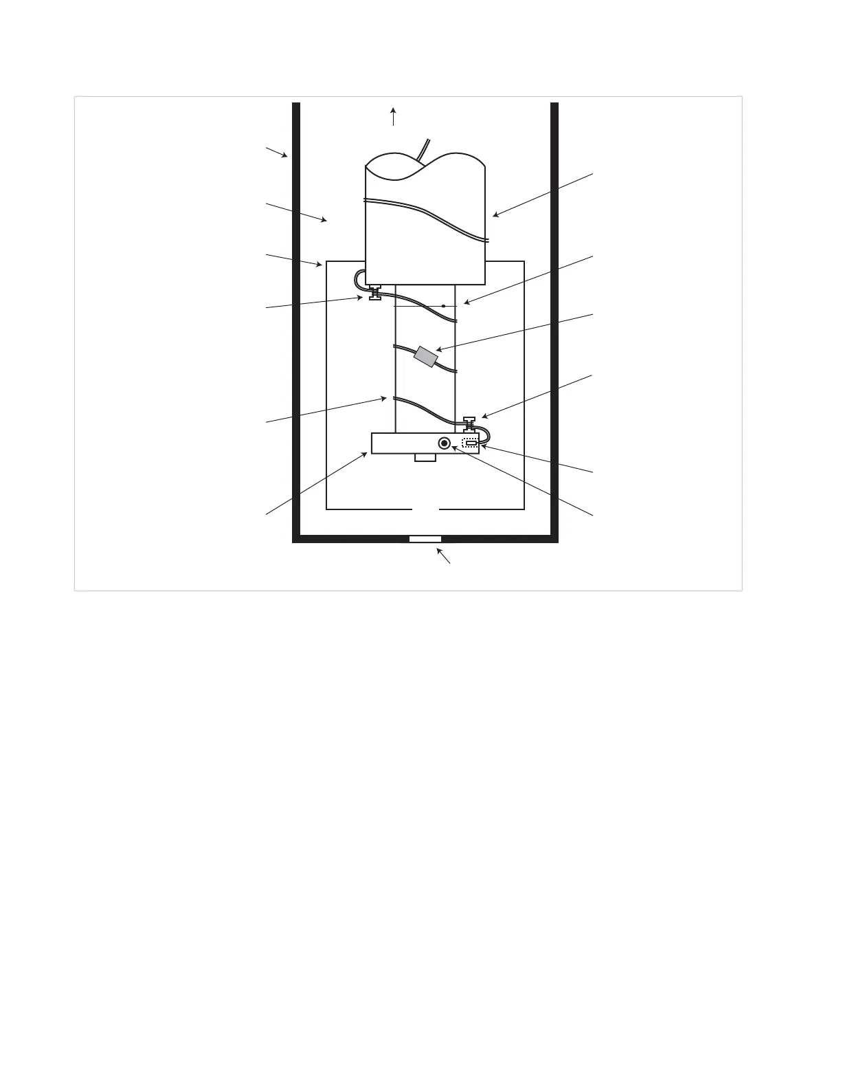
FIGURE 2-1 Typical sensor installation in a mechanical refrigerator
Vacuum shroud
Vacuum space
Radiation shield
Second stage and
sample holder
Thermal anchor
(bobbin)
Cryogenic wire
(small diameter, large AWG)
To room
temperature
Refrigerator
first stage
Sensor
Thermal anchor
(bobbin)
Heater
(wiring not shown
for clarity)
Optical window
(if required)
Dental floss
tie-down
-or-
Cryogenic
tape
Drawing not to scale