38 cHAPTER 3: Installation
Model 336 Temperature Controller
Remove all insulation, then tighten the screws on the thermocouple wires. Keep the
ceramic terminal blocks away from heat sources including sunlight and shield them
from fans or room drafts.
3.7.2 Thermocouple
Installation
Thermocouples are commonly used in high-temperature applications. Cryogenic use
of thermocouples offers some unique challenges. A general installation guideline is
provided in section 2.4. Consider the following when using thermocouples at low
temperatures:
D Thermocouple wire is generally more thermally conductive than other sensor
lead wire. Smaller gauge wire and more thermal anchoring may be needed to
prevent leads from heating the sample.
D Attaching lead wires and passing them through vacuum tight connectors is often
necessary in cryogenic systems. Remember, the thermocouple wire is the sensor;
any time it joins or contacts other metal, there is potential for error.
D Temperature verification and calibration of room temperature compensation is
difficult after the sensor is installed. When possible, keep a piece of scrap wire
from each installation for future use.
D Thermocouples can be spot-welded to the cryostat for good thermal anchoring as
long as the cryostat has a potential close to earth ground.
3.7.3 Grounding and
Shielding
Care must be taken to minimize the amount of noise contributed by ground loops,
when grounding thermocouple inputs. For lowest measurement noise, do not ground
thermocouple sensors. The instrument operates with slightly more noise if one of the
thermocouples is grounded. Be sure to minimize loop area when grounding both
thermocouples. The instrument does not offer a shield connection on the terminal
block. Twisting the thermocouple wires helps reject noise. If shielding is necessary,
extend the shield from the oven or cryostat to cover the thermocouple wire, but do
not attach the shield to the instrument.
3.8 Heater Output
Setup
The following section covers the heater wiring from the vacuum shroud to the instru-
ment for both heater outputs. Specifications are detailed in section 1.3. For help on
choosing and installing an appropriate resistive heater, refer to section 2.5.
3.8.1 Heater Output
Description
Both powered heater outputs (Outputs 1 and 2) are traditional control outputs for a
cryogenic temperature controller. Both are variable DC current sources with software
settable ranges and limits. Both are configurable for optimization using either a 25 )
or a 50 ) heater resistance. At the 50 ) setting, both outputs are limited to a maxi-
mum output current of 1 A. At the 25 ) setting, the maximum heater output current
is 2 A for Output 1, and 1.41 A for Output 2. The compliance voltage of each output is
50 V minimum, but can reach as high as 58 V if the heater resistance is higher than
the nominal setting. Heater power is applied in one of three ranges: high, med, or low.
Each range is one decade lower in power. Refer to TABLE 4-14 for maximum current
and power ratings into different heater resistance.
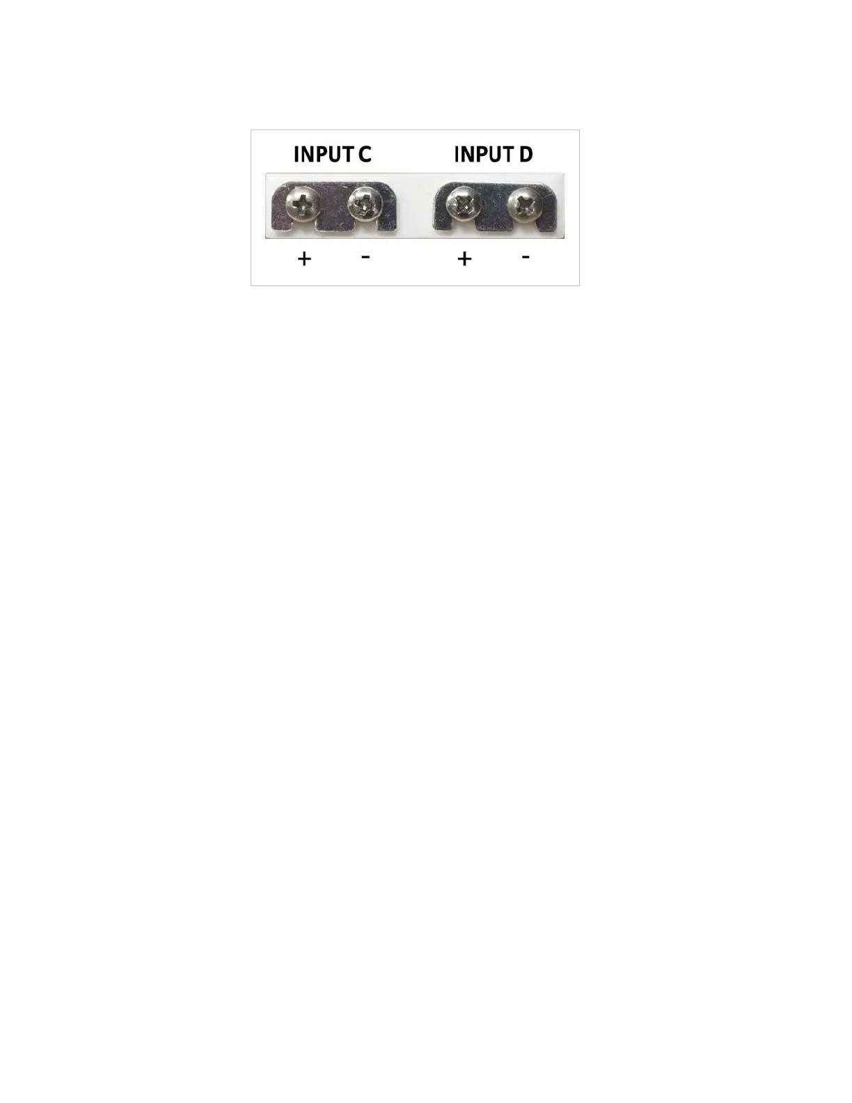
FIGURE 3-8 Thermocouple input definition and
common connector polarities (inputs shown shorted)
 Loading...


