2.5.1 Heater Resistance and Power 21
| www.lakeshore.com
surface of the vacuum shroud on its outer surface, so some cooling power must be
directed to the shield to keep it near the load temperature. If the cooling system does
not include an integrated radiation shield (or one cannot be easily made), one
alternative is to wrap several layers of super-insulation (aluminized mylar) loosely
between the vacuum shroud and load. This reduces radiation transfer to the
sample space.
2.5 Heater
Selection and
Installation
There is a variety of resistive heaters that can be used as the controlled heating source
for temperature control. The mostly metal alloys like nichrome are usually wire or foil.
Shapes and sizes vary to permit installation into different systems.
2.5.1 Heater Resistance
and Power
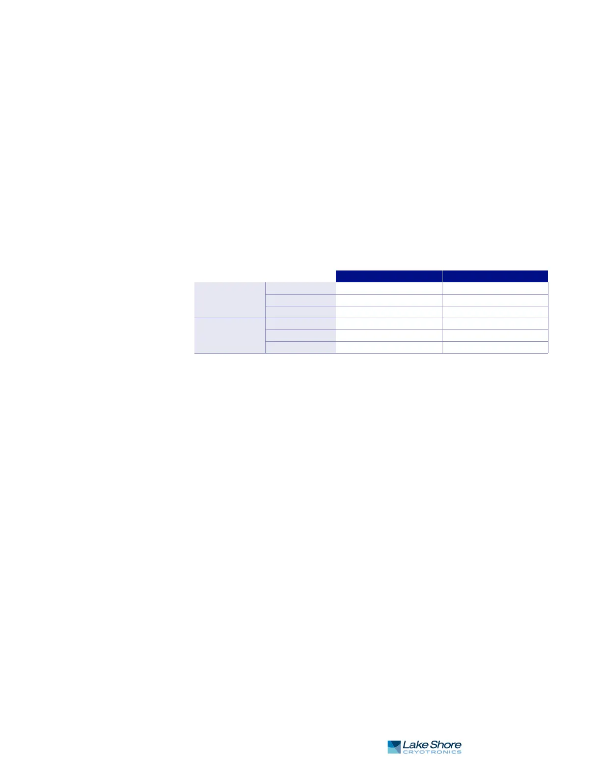
Cryogenic cooling systems have a wide range of cooling power. The resistive heater
must be able to provide sufficient heating power to warm the system. The Model 336
can provide up to 100 W of power from Output 1 and up to 50 W of power from
Output 2. TABLE 2-2 provides the current and voltage limits, as well as the resulting
maximum power for each output for the 25 ) and 50 ) settings, using nominal
heater load values.
Even though the Model 336 heater outputs are current sources, they have a limit of
50 V (called the compliance voltage). This compliance voltage also limits maximum
power. So for heaters values other than 25 ) or 50 ), calculate the maximum power
using the following equations: P = I
2
R and P = V
2
/R, where P is maximum power, I is
max current, V is max voltage, and R is the heater resistance. The current and voltage
limits are in place at the same time, so the smaller of the two computations gives the
maximum power available to the heater.
Example 1: A 20 ) heater is connected to Output 1, and the heater resistance setting
is set to 25 ), which can provide up to 2 A of current, and up to 50 V.
The power limit is the smaller of the two, or 80 W, limited by current.
Example 2: A 60 ) heater is connected to Output 2, and the heater resistance setting
is set to 50 ), which can provide up to 1 A of current, and up to 50 V.
The power limit is the smaller of the two, or 41.7 W, limited by voltage.
25) setting (25 ) heater) 50 ) setting (50 ) heater)
Output 1
Current limit 2 A 1 A
Voltage limit 50 V 50 V
Max power 100 W 50 W
Output 2
Current limit 1.41 A 1 A
Voltage limit 50 V 50 V
Max power 50 W 50 W
TABLE 2-2 Current and voltage limits with resulting max power
Current Limit Voltage Limit:
P = I
2
RP = V
2
/R
P = (2 A)
2
x (20 )) P = (50 V)
2
/(20 ))
P = 80 W P = 125 W
Current Limit Voltage Limit:
P = I
2
RP = V
2
/R
P = (1 A)
2
x (60 )) P = (50 V)
2
/(60 ))
P = 60 W P = 41.7 W