82 cHAPTER 5: Advanced Operation
Model 336 Temperature Controller
5.7.2 Relays
There are two relays on the Model 336 numbered 1 and 2. They are most commonly
thought of as alarm relays, butthey may be manually controlled also. Relay assign-
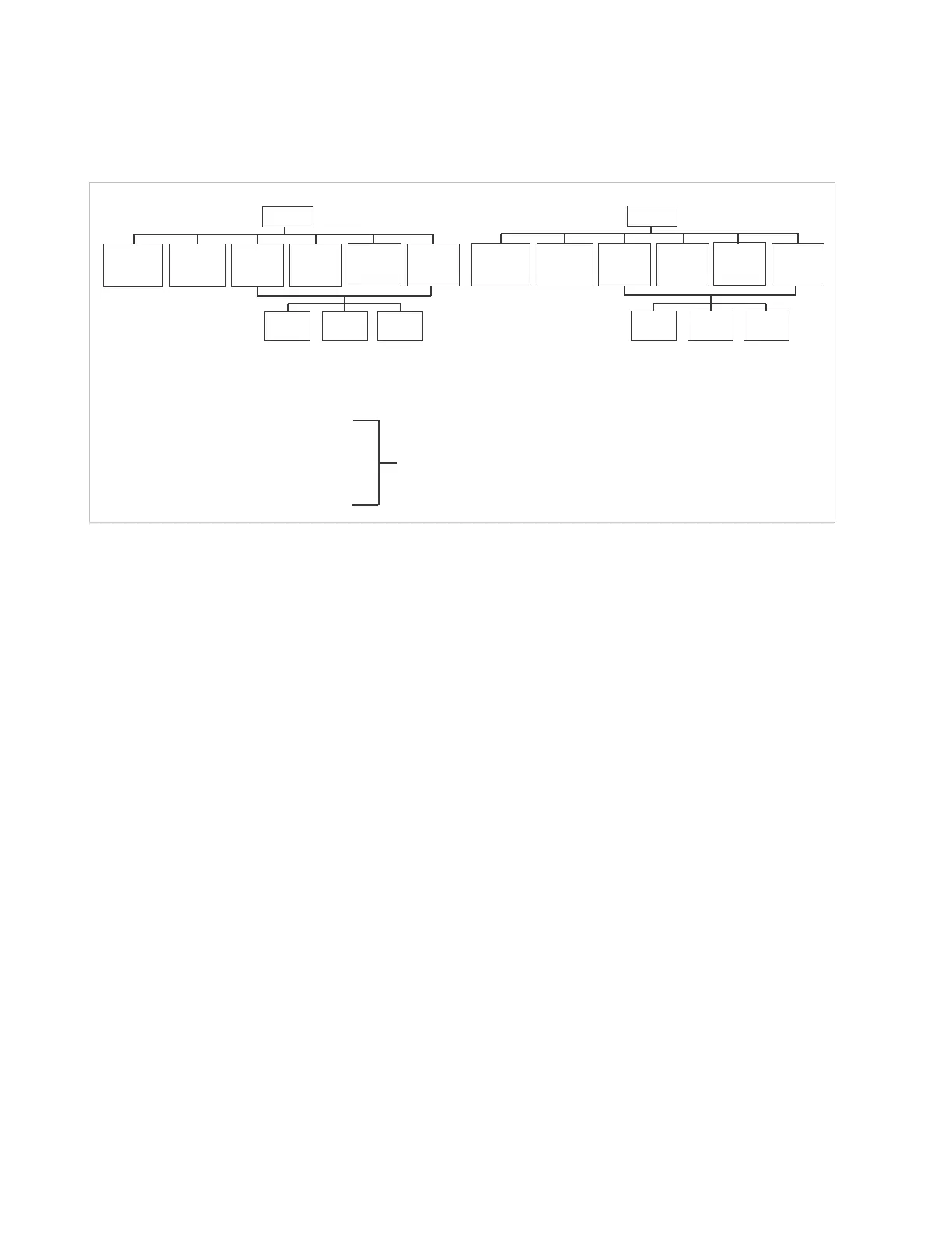
ments are configurable as shown in FIGURE 5-6. Two relays can be used with one sen-
sor input for independent high and low operation, or each can be assigned to a
different input.
When using relays with alarm operation, set up alarms first. The relays are rated for
30 VDC and 3 A. Their terminals are in the detachable terminal block on the
Model 336 rear panel.
In the Off mode, the relay is un-energized, leaving the normally open (NO) contacts
open and the normally closed (NC) contacts closed. In the On mode, the relay is ener-
gized, so the NO contacts will be closed and the NC contacts will be open. In the Alarm
mode the relay will activate based on the state of the configured Alarm Input sensor.
When the Alarm to Follow parameter is set to Low, the relay will energize if the con-
figured Alarm Input sensor goes into a low alarm state. If it is set to High, the relay will
energize if the configured Alarm Input sensor goes into a high alarm state. If the
Alarm to Follow parameter is set to Both, the relay will energize if the configured
Alarm Input sensor goes into either a low alarm or a high alarm state.
Menu Navigation:
RelaysQ(Relay 1, Relay 2)QModeQ(Off, On, Alarm)
RelaysQ(Relay 1, Relay 2)QAlarm InputQInput (A, B, C, D)
RelaysQ(Relay 1, Relay 2)QAlarm to FollowQ(Low, High, Both)
Default: ModeQOff
Alarm InputQInput A
Alarm to FollowQBoth
Interface Command: RELAY
5.8 Curve
Numbers and
Storage
The Model 336 has 20 standard curve locations, numbered 1 through 20. At present,
not all locations are occupied by curves; the others are reserved for future updates. If
a standard curve location is in use, the curve can be viewed using the view operation.
Standard curves cannot be changed by the user, and reserved locations are not avail-
able for user curves.
FIGURE 5-6 Relay settings
Off Manual off—relay remains in the normal state
On Manual on—relay remains in the active state
A Alarm Relay will follow Input A alarms
B Alarm Relay will follow Input B alarms
C Alarm Relay will follow Input C alarms
D Alarm Relay will follow Input D alarms
Relay 1 Relay 2
Off
Manual off
relay remains in
normal state
On
Manual on
relay remains in
active state
A Alarm
Follows
Input A
B Alarm
Follows
Input B
Off
Manual off
relay remains in
normal state
On
Manual on
relay remains in
active state
A Alarm
Follows
Input A
B Alarm
Follows
Input B
Both
Alarms
Low
Alarm
High
Alarm
Both
Alarms
Low
Alarm
High
Alarm
C Alarm
Follows
Input C
D Alarm
Follows
Input D
C Alarm
Follows
Input C
D Alarm
Follows
Input D
Both Alarms Relay active when either the High or Low Alarm is active
Low Alarms Relay active only when the Low Alarm is active
High Alarms Relay active only when the High Alarm is active


 To Next Page