5.7.1 Alarms 81
| www.lakeshore.com
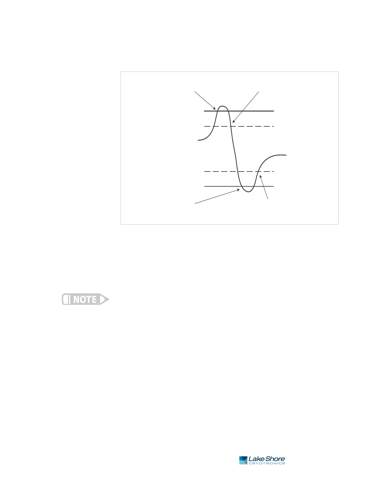
FIGURE 5-5 illustrates the interaction between alarm setpoint and dead band in
non-latching operation. With the high alarm setpoint at 100 K and the dead band
at 5 K, the high alarm triggers when sensor input temperature increases to 100 K,
and it will not deactivate until temperature drops to 95 K. In addition, the same
5 K dead band is applied to the low alarm setpoint as well.
To setup an alarm, enter the Alarm Setup menu by pressing the Alarm key. If a latching
alarm has been activated, you will be prompted with a Reset Alarm? message. Select
No to enter the Alarm Setup menu.
Menu Navigation:
AlarmQInput (A, B, C, D)QLatchingQ(Off, On)
AlarmQInput (A, B, C, D)QDeadbandQ(see note below)
Low and High Setpoint limits are determined by the Preferred Units of the associated
sensor input.
Default: LatchingQOff
DeadbandQ1.0000 K
Interface Command: ALARM
FIGURE 5-5 Dead band example
High alarm activated
Low alarm activated
Low alarm setpoint
Temperature reading
High alarm setpoint
High alarm deactivated
100 K
95 K
55 K
50 K
Low alarm deactivated
Deadband = 5 K
Alarm latching off
 Loading...


