32 cHAPTER 3: Installation
Model 336 Temperature Controller
Always turn off the instrument before making any rear panel connections. This is espe-
cially critical when making sensor to instrument connections.
3.4 Line Input
Assembly
This section describes how to properly connect the Model 336 to line power. Please
follow these instructions carefully to ensure proper operation of the instrument and
the safety of operators.
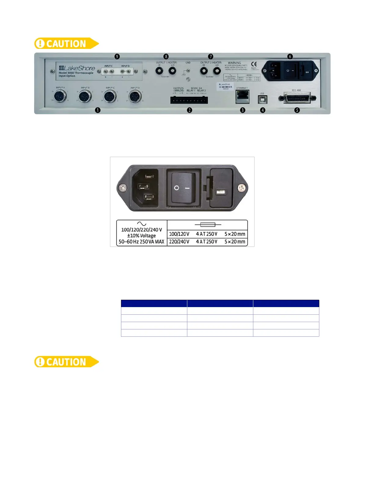
3.4.1 Line Voltage
The Model 336 has four different AC line voltage configurations so that it can be oper-
ated from line power anywhere in the world. The nominal voltage and voltage range
of each configuration is shown below. (The recommended setting for 230 V operation
is 240 V.)
AC line voltage is set at Lake Shore, but it is good to verify that the AC line voltage indica-
tor in the fuse drawer window is appropriate before turning the instrument on. The
instrument may be damaged if turned on with the wrong voltage selected. Also remove
and verify that the proper fuse is installed before plugging in and turning on the instru-
ment. Refer to section 8.5 for instructions on changing the line voltage configuration.
3.4.2 Line Fuse and
Fuse Holder
The line fuse is an important safety feature of the Model 336. If a fuse ever fails, it is
important to replace it with the value and type indicated on the rear panel for the line
voltage setting. The letter T on the fuse rating indicates that the instrument requires
a time-delay or slow-blow fuse. Fuse values should be verified any time line voltage
configuration is changed. Refer to section 8.6 for instructions for changing and verify-
ing a line fuse.
FIGURE 3-1 Model 336 rear panel
FIGURE 3-2 Line input assembly
Nominal Minimum Maximum
100 V 90 V 110 V
120 V 108 V 132 V
220 V 198 V 242 V
240 V 216 V 264 V
TABLE 3-1 Line voltage