3.4.3 Power Cord 33
| www.lakeshore.com
3.4.3 Power Cord
The Model 336 includes a 3-conductor power cord that mates with the IEC 320-C14
line cord receptacle. Line voltage is present on the two outside conductors and the
center conductor is a safety ground. The safety ground attaches to the instrument
chassis and protects the user in case of a component failure. A CE approved power
cord is included with instruments shipped to Europe; a domestic power cord is
included with all other instruments (unless otherwise specified when ordered).
Always plug the power cord into a properly grounded receptacle to ensure safe instru-
ment operation.
The delicate nature of measurements being taken with this instrument may necessi-
tate additional grounding including ground strapping of the instrument chassis. In
these cases the operators safety should remain the highest priority and low imped-
ance from the instrument chassis to safety ground should always be maintained.
3.4.4 Power Switch
The power switch is part of the line input assembly on the rear panel of the Model 336
and turns line power to the instrument on and off. When the circle is depressed,
power is off. When the line is depressed, power is on.
3.5 Diode/Resistor
Sensor Inputs
This section details how to connect diode and resistor sensors to the Model 336 stan-
dard inputs and the Model 3062 4-channel scanner option card input channels. Refer
to section 4.4 to configure the inputs. Refer to section 3.6 for a description of the
optional capacitance input and section 3.7 for a description of the thermocouple
input.
3.5.1 Sensor Input
Connector and Pinout
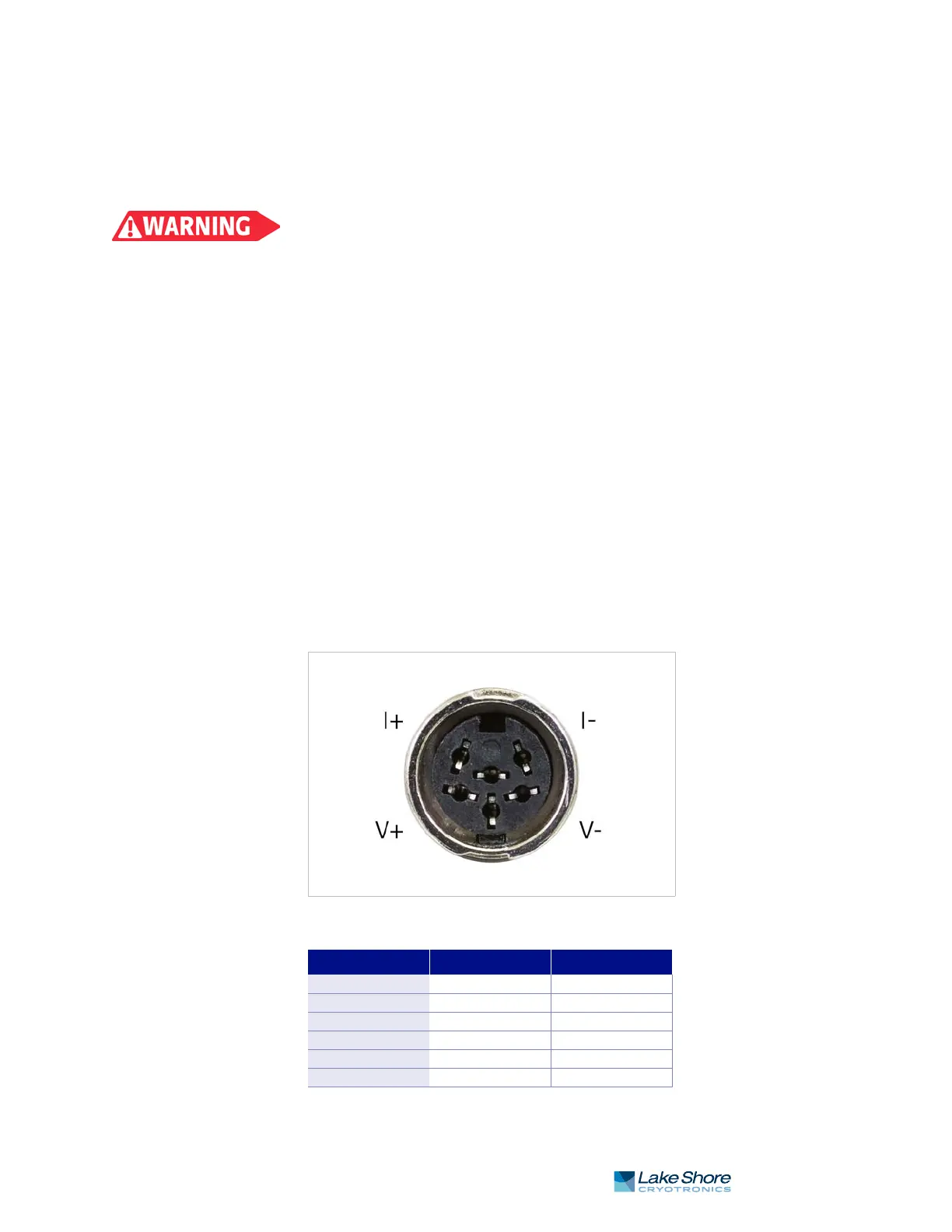
The input connectors are 6-pin DIN 45322 sockets. The sensor connector pins are
defined in FIGURE 3-3 and TABLE 3-2. Four mating connectors (6-pin DIN plugs) are
included in the connector kit shipped with the instrument. These are common con-
nectors, so additional mating connectors can be purchased from local electronics
suppliers. They can also be ordered from Lake Shore as G-106-233.
FIGURE 3-3 Sensor input connector
Pin Symbol Description
1 I– –Current
2 V– –Voltage
3 None Shield
4 V+ +Voltage
5 I+ +Current
6 None Shield
TABLE 3-2 Diode/resistor input connector details