7. 5 R a ck M oun t ing 149
| www.lakeshore.com
7.5 Rack Mounting
The Model 336 can be installed into a 482.6 mm (19 in) rack mount cabinet using the
optional Lake Shore Model RM-1 Rack Mount Kit. The kit contains mounting ears,
handles and screws that adapt the front of the instrument to fit into a 88.9 mm
(3.5 in) tall, full rack space. Additional support may be required in the rear of the
instrument and to relieve strain on heavy cables. The mounting ears are painted and
do not guarantee good electrical contact between the instrument and cabinet. They
should not be used for ground strapping unless paint is removed from under all
screws.
Ensure that there is a 25 mm (1 in) clearance on both sides of the instrument after
rack mounting.
7.6 Input Option
Card Installation
The field installable Model 3060 adds thermocouple functionality to inputs C and D,
the Model 3061 adds capacitance functionality to input D, and the Model 3062 adds
4 scanners to input D. While the options can be easily removed, this is not necessary
as the standard inputs remain fully functional when they are not being used to mea-
sure thermocouple or capacitance temperature sensors. Calibration for the options
are stored on the card so you can install it in the field and use it with multiple
Model 336 temperature controllers without recalibration.
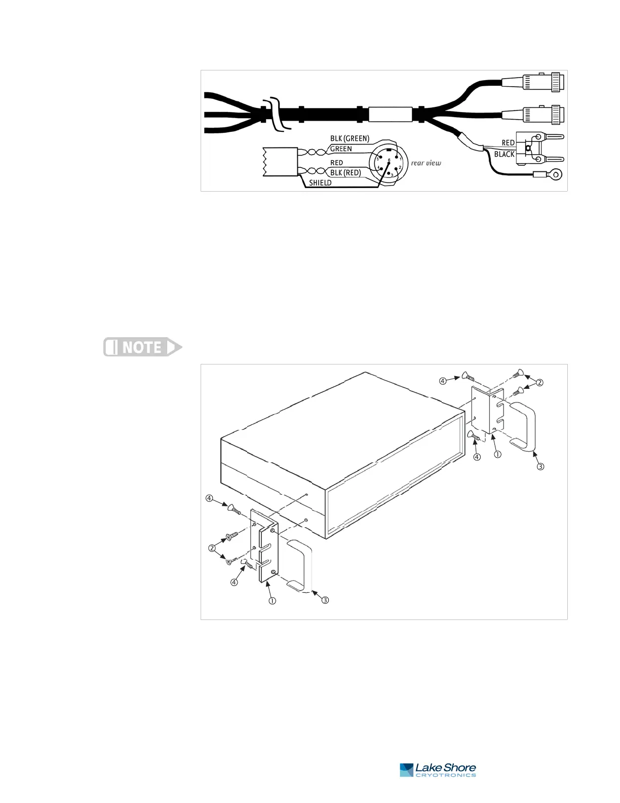
FIGURE 7-1 Model 336 sensor and heater cable assembly
10 ft: P/N 112-177, 20 ft: P/N 112-178, 33 ft: P/N 112-180
FIGURE 7-2 Model RM-1 rack mount kit
Item Description PN Qty
Rack mount ear 107-440 2
* Screw, 6-32×3/8, PH, FLHD, MS, SS 0-033 4
Rack mount handles, 3 in, black 107-433 2
Screw, 8-32×3/8, PH, FLHD, MS, SS 0-081 4
*Remove and discard 4 screws from case; replace with 4 screws from kit


 To Next Page