3.8.5 Po wering Ou tp uts 3 and 4 U si ng an Exte rn al Pow er Supply 41
| www.lakeshore.com
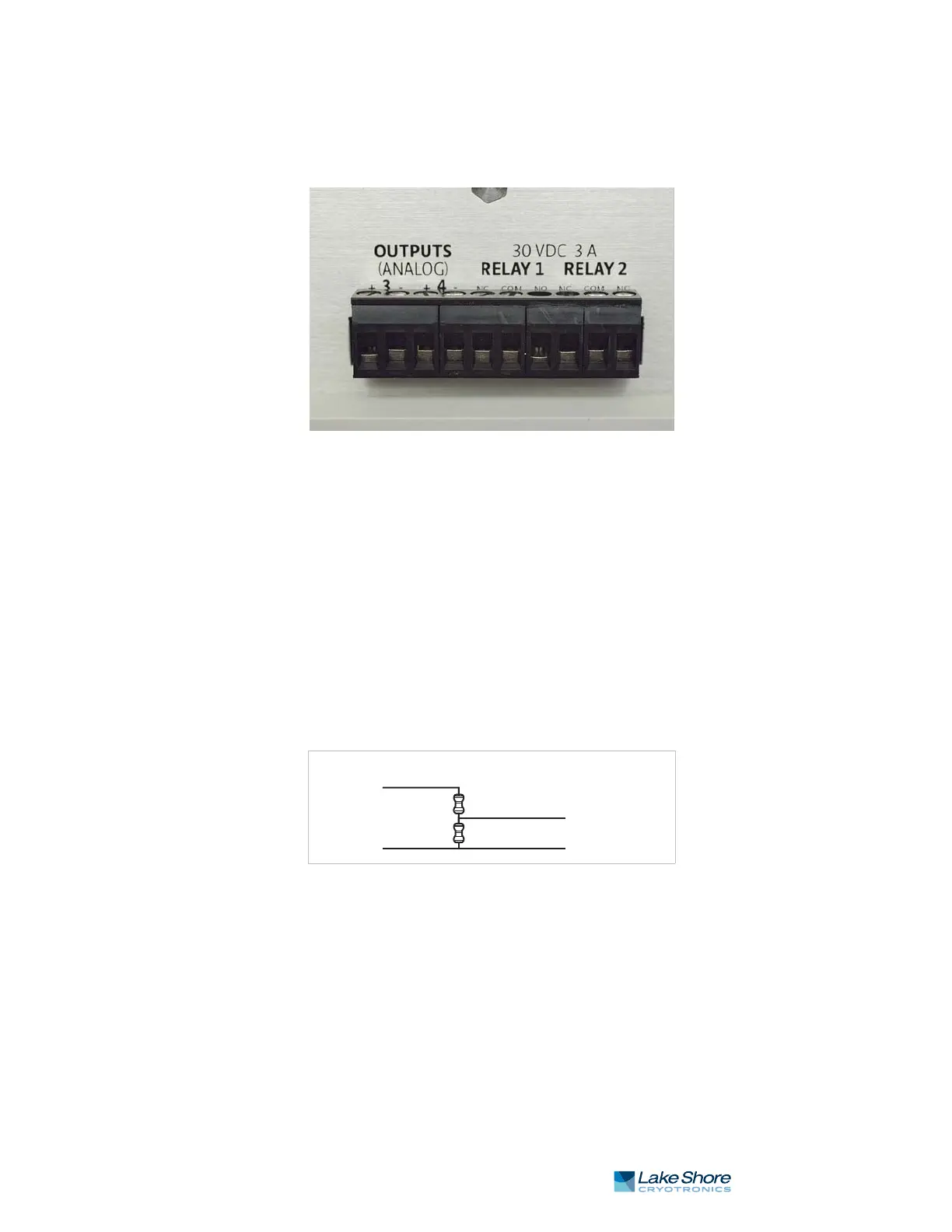
3.8.5.3 Connecting to the Model 336
The voltage programming cable attaches to the removable terminal block on the rear
panel of the Model 336 (FIGURE 3-10). Output number and polarity of the output
leads are indicated on the silk screen. The negative (–) terminals are connected inter-
nally to the instrument chassis to provide a ground reference.
In the most basic configuration, a two-conductor cable connects directly from the
output terminals to the power supply programming input. Copper wire size
20 AWG to 26 AWG is recommended.
3.8.5.4 Programming Voltages Under 10 V
A voltage divider FIGURE 3-11 can be used to reduce the control output voltage if the
programming input of the power supply has a range of less than 0 V to 10 V to ensure
full output resolution, and protection against overloading the external supply pro-
gramming inputs. The output voltage is proportional to the ratio of resistors
R1 to R2: Vout = 10V x R1/(R1+R2). It is also important to keep the sum of R1 + R2 >
1000 ) or the Model 336 output may not reach the output voltage setting due to
internal overload protection. For a programming input range of 0 V to 5 V, recom-
mended values are: R1 = R2 = 2000 ). For a programming input range of 0 V to 1 V,
recommended values are: R1 = 500 ), R2 = 4500 ). Exact resistor value, type and tol-
erance are generally not important for this application.
FIGURE 3-10 Output terminal block
FIGURE 3-11 Voltage divider circuit for Output 3
Model 350
Output 3+
Output 3–
Power supply
Program input+
Program input–
R2
R1