PLMNL0199 REV. J Effective Date: 08/05/21 7 FiberCUT
®
ST Operation Manual
3 Installation – Electrical
Figure 12
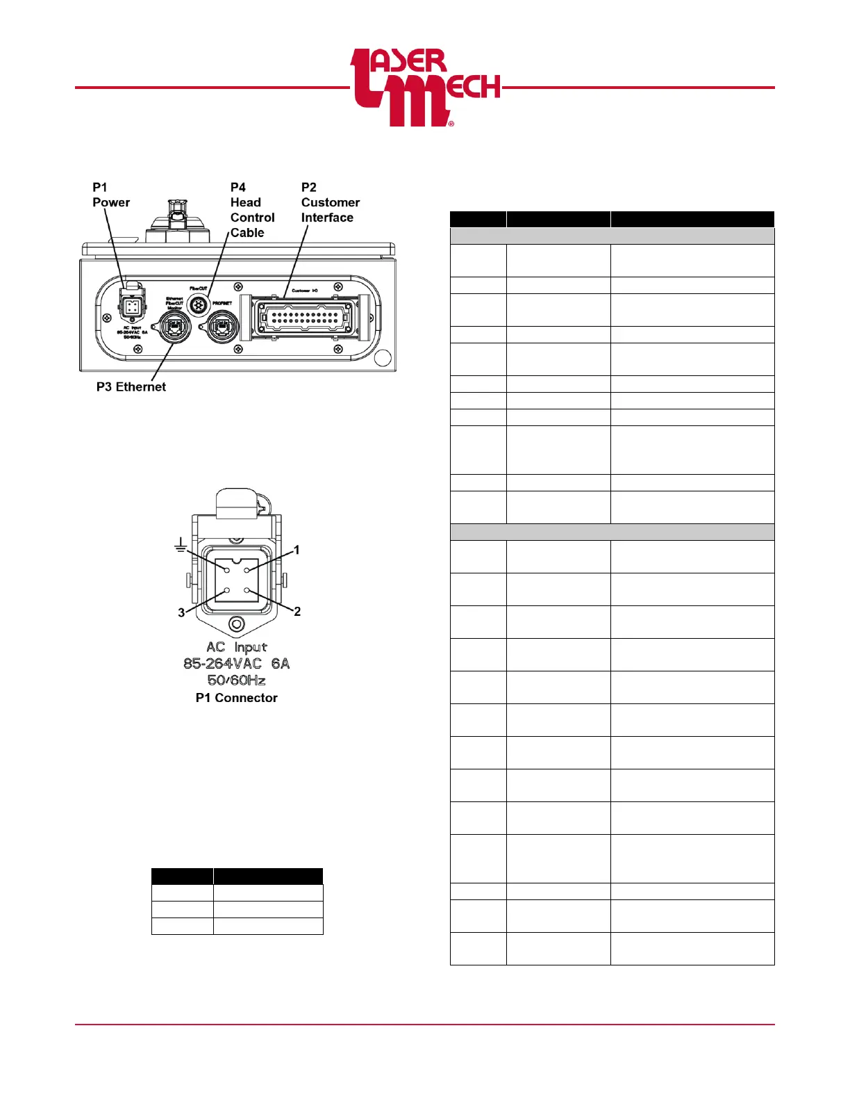
3.1 Power (P1)
Specifications: 85 to 264VAC, 50/60Hz,
6A
Figure 13
Power to the FiberCUT
®
controller is
connected using P1 (4-pin connector) on
the bottom left side of the control box. A
power cord is included with the system,
however alteration of this connection may
be preferred based on specific installation
requirements.