PLMNL0199 REV. J Effective Date: 08/05/21 30 FiberCUT
®
ST Operation Manual
5 FiberCUT
®
Monitor
FiberCUT
®
Monitor is a very useful tool for use
with your FiberCUT
®
head. FiberCUT
®
Monitor
runs on a standard PC and connects to the
controller with an Ethernet cable. It provides real
time monitoring of the tip standoff, head position,
head temperatures and I/O of your FiberCUT
®
on a single, easy-to-read screen.
See Section 5.4 for the standard (single)
view style panel.
See Section 5.5 for the multiple view style
panel.
5.1 Installation
Download the latest copy of FiberCUT
®
Monitor RS and FiberCUT
®
Controller
Firmware Update (FiberCUT
®
Update) from
the FiberCUT
®
Updates web page:
http://www.lasermech.com/fibercutupdates
After you download the compressed folders
from the web site they only need to be
decompressed.
1. Right-click on each compressed folder
and select Extract All....
2. Follow the on-screen instructions to
complete the decompression
(extraction) of the compressed files.
The FiberCUT
®
update (SW0012)
folder will have a single executable file.
The FiberCUT
®
Monitor folder will have
a single FiberCutMonitorRS.exe file,
several dll files and a folder named
FiberCUTMonitorRS Libs.
It is important that the Libs folder and
all the dll files remain at the same
location as FiberCUT
®
Monitor.
The parent folder for these files can be
moved and copied as needed. No
license key is needed.
3. There is a communications driver
provided in the Driver folder.
If you are unable to locate or connect
to the system when running FiberCUT
®
Monitor, exit the program and run the
driver installer.
5.2 System Requirements
Windows 7 or later
64-bit Operating System*
Screen Resolution:
– Standard View: Minimum 800 x 600
– Multiple View: Minimum 1280 x 768
Ethernet Port
* An older version of the software
supporting 32-bit operating systems is
available upon request.
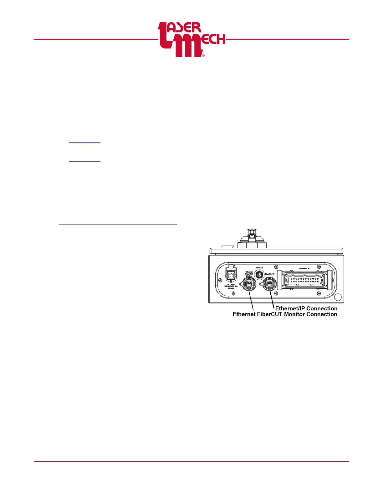
5.3 Preparing to Connect
An Ethernet cable makes all
communications between FiberCUT
®
Monitor and the FiberCUT
®
head. See
Figure 33.
Figure 33
You can connect the FiberCUT
®
controller directly to a PC.
You can connect multiple FiberCUT
®
controllers to a PC using an Ethernet
Switch.
o Connecting the FiberCUT
®
controller to a wider network, which
may include an internet connection,
is also possible. This type of
connection adds a level of
complexity due to the high level of
network traffic.