PLMNL0199 REV. J Effective Date: 08/05/21 16 FiberCUT
®
ST Operation Manual
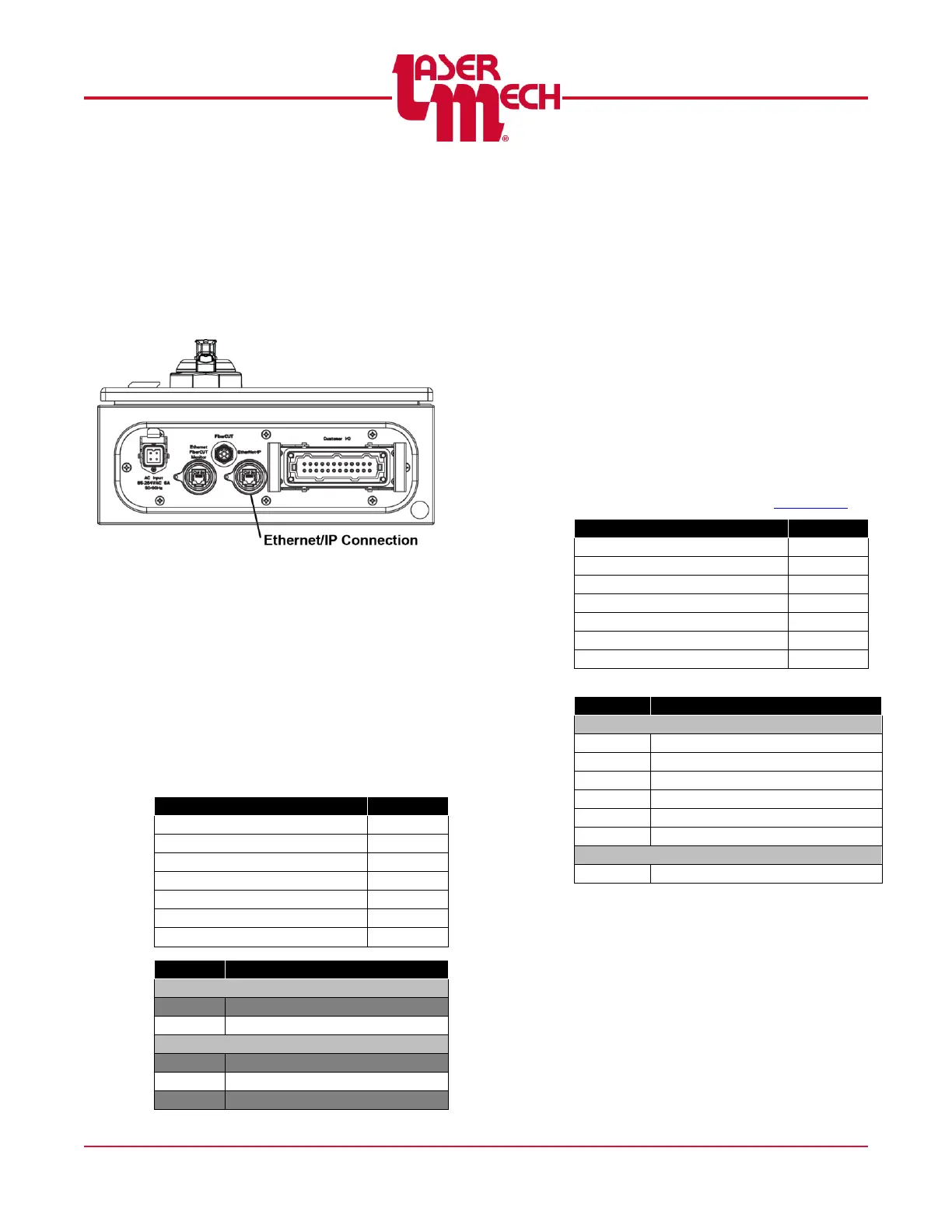
3.9.1 EtherNet/IP
The connection to the EtherNet/IP
uses an RJ45 jack in the FiberCUT
®
controller. Do not confuse the
EtherNet/IP with the computer
Ethernet interface used for FiberCUT
®
Monitor. See Figure 19.
Figure 19
PLCSA0023 Configuration
The FiberCUT
®
controller without an
external power switch consists of an
Allen Bradley 1734-AENT Point I/O
module.
Set the IP Address using the switches
on the module or software provided by
Allen Bradley. Refer to Allen Bradley
Publication ENET-UM001N-EN-P for
more information.
Configuration Size (Bytes)
PLCSA0046 Configuration
The FiberCUT
®
controller with an
external power switch consists of a
HMS Industrial Networks Anybus IC
EIP module and Interconnect Board.
Set the IP Address using the rotary
switches S1 (x10) and S2 (x1) on the
Interconnect Board to addresses
ranging from 192.168.1.1-
192.168.1.99 on Subnet
255.255.255.0.
The default value is DHCP. Selecting
a value of 00 allows you to configure
the IP Address using Fieldbus
Settings on the Preferences page of
FiberCUT
®
Monitor. See Section 5.6.
Configuration Size (Bytes)
Lower Assembly Temperature