PLMNL0199 REV. J Effective Date: 08/05/21 17 FiberCUT
®
ST Operation Manual
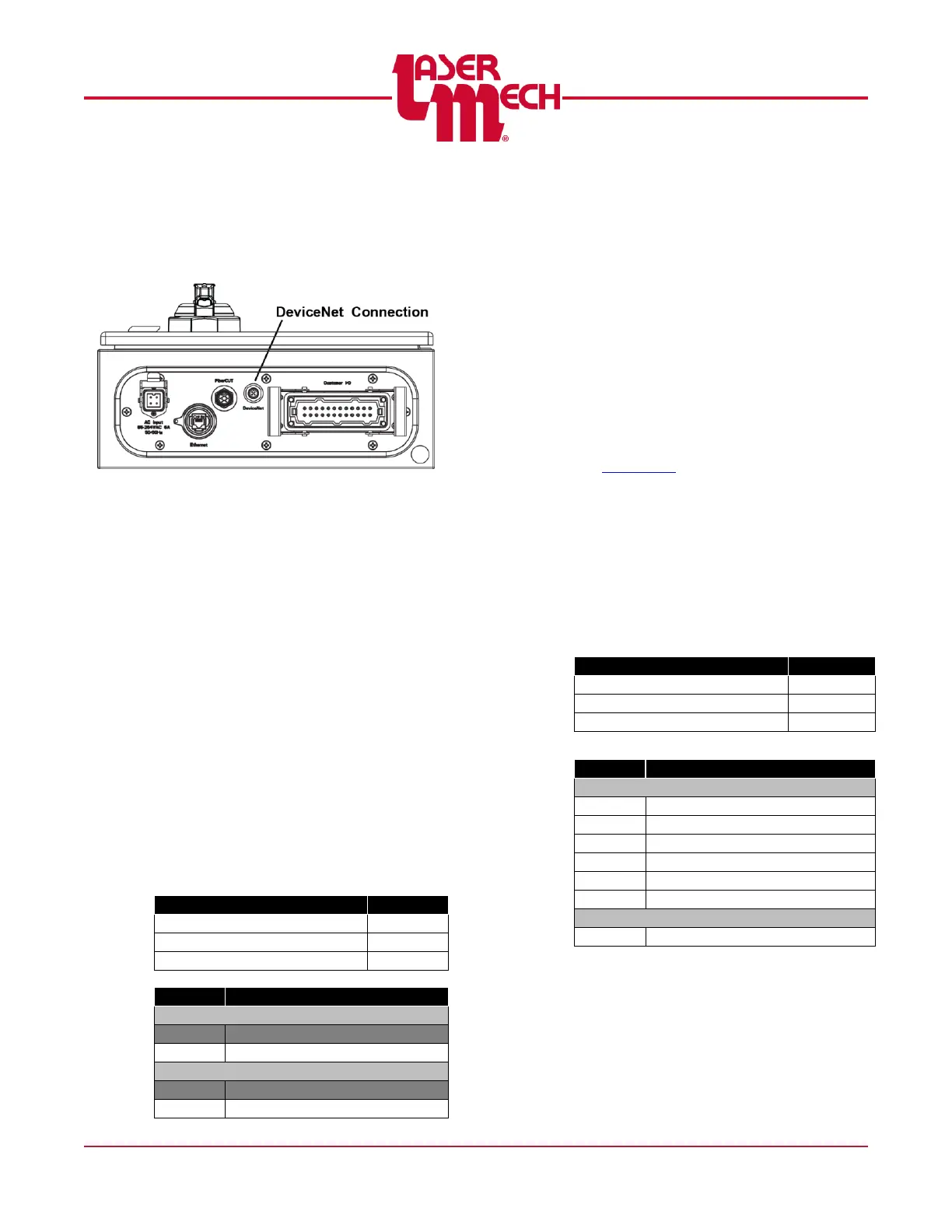
3.9.2 DeviceNet
The connection to the DeviceNet I/O
uses a 5-pin micro connector located
in the bottom corner of the control
box. See Figure 20.
Figure 20
PLCSA0015 Configuration
The FiberCUT
®
controller without an
external power switch consists of an
Allen Bradley 1734-ADN Point I/O
module preconfigured to appear on
Node 12. Refer to Allen Bradley
Publication 1734-UM002C-EN-P for
more information on configuring the
module.
A termination resistor is fitted on the
terminal block of the I/O module in the
FiberCUT
®
controller. (S5 on new
controllers).
If this device is the last node in the
system, then the terminating
resistor remains in place.
If this device is not the last node in
the system, it is necessary to
remove this resistor.
PLCSA0044 Configuration
The FiberCUT
®
controller with an
external power switch consists of a
HMS Industrial Networks Anybus IC
DEV module and Interconnect Board.
Set the Node Address using the rotary
switches S1 (x10) and S2 (x1) on the
Interconnect Board to addresses
ranging from 01-63.
Selecting a value of 00 allows you to
configure the Node Address using
Fieldbus Settings on the Preferences
page of FiberCUT
®
Monitor. See
Section 5.6.
A termination resistor is fitted on the
Interconnect Board and is controlled
using switch S5.
If this device is the last node in the
system, then S5 should be ON.
If this device is not the last node in
the system, then S5 should be
OFF.