PLMNL0199 REV. J Effective Date: 08/05/21 15 FiberCUT
®
ST Operation Manual
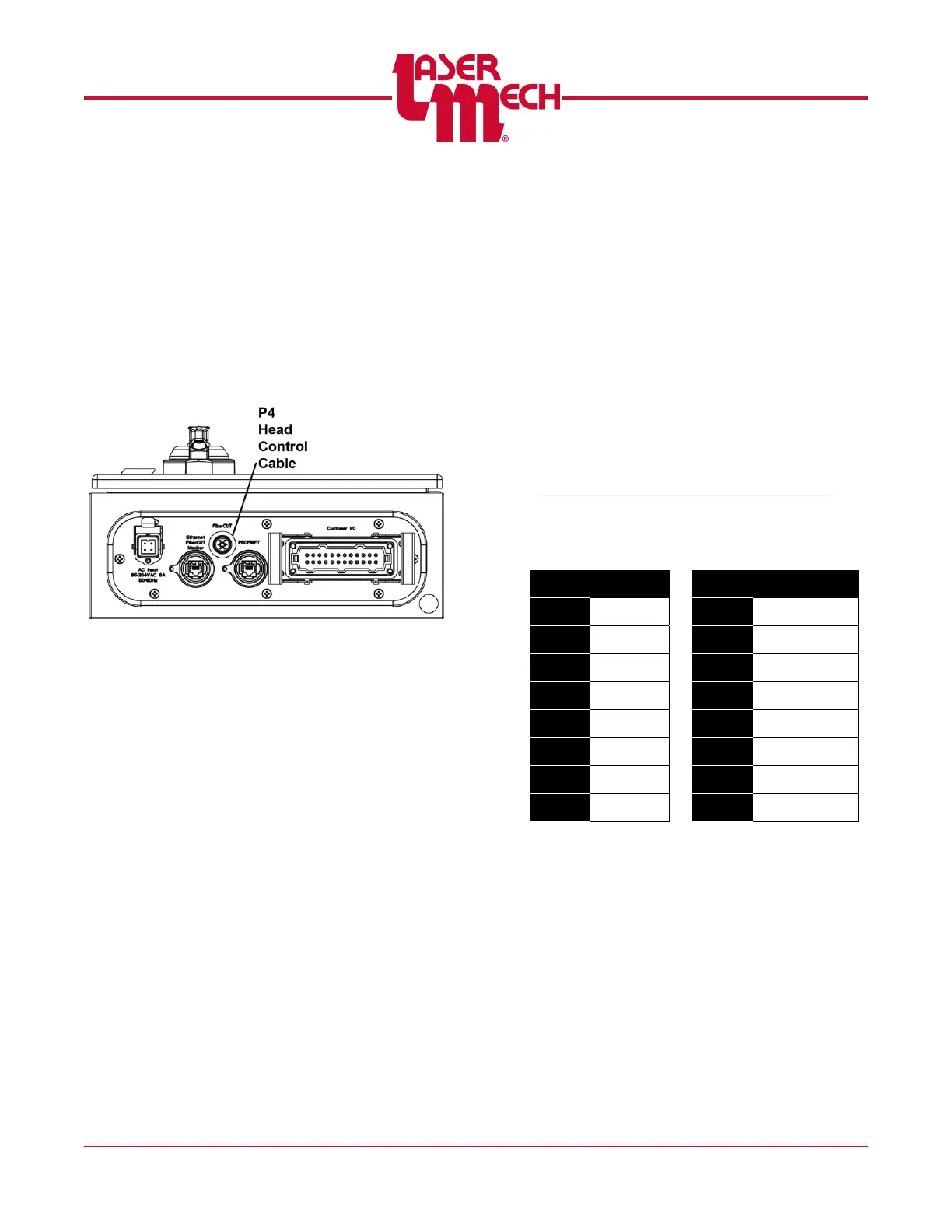
3.8 Head-Control Cable (P4)
A straight through 14-conductor cable
(PLCAB0489) connects the FiberCUT
®
head to the controller. See Figure 18.
Route this cable away from high power and
high voltage wires to prevent interference.
This cable is a high-flex cable designed for
robotic applications, but minimizing the
amount of exposure to movement and
flexing can increase the life of the cable.
Figure 18
3.9 Remote I/O Options
The remote I/O option in the FiberCUT
®
controller simplifies the hardware
integration into the laser processing cell.
Instead of using the discrete I/O
connections in the customer I/O connector,
the integration can consist of a relatively
simple cable. Four different protocols are
available to support most industrial
networks.
Device configuration files (EDS or
GSD) and supplemental manuals are
available for download from the
FiberCUT
®
Updates web page:
http://www.lasermech.com/fibercutupdates
All remote I/O options include the
digital inputs and digital outputs shown
below.
Some controllers also include analog
voltage and temperature readings for
monitoring purposes. Voltages are
reported as 12-bit numbers, where 0-
4095 = 0-5V. Temperatures are
reported as hundredths of degrees
Celsius, where 0-7000 = 0.00-70.00°C.
The (4) sections that follow provide
specific data mappings for each
controller configuration.