PLMNL0199 REV. J Effective Date: 08/05/21 2 FiberCUT
®
ST Operation Manual
2 Installation – Mechanical
2.1 Robotic Mount
The robotic mount attaches to the robot
and can provide optional collision sensing
to protect the cutting head during a crash.
See Figure 3. The collision sensor mounts
to the robot using an adapter plate. The
appropriate hardware will be provided with
the cutting head determined at the time of
sale.
Figure 3
The optional collision sensor (sold
separately as part number PLCPD0084) is
a pneumatic device.
The sensor requires 6mm OD hose.
The recommended operating pressure
for the collision sensor is 1 BAR, but
can vary depending on application.
The hoses need to be suitable for
robotic applications.
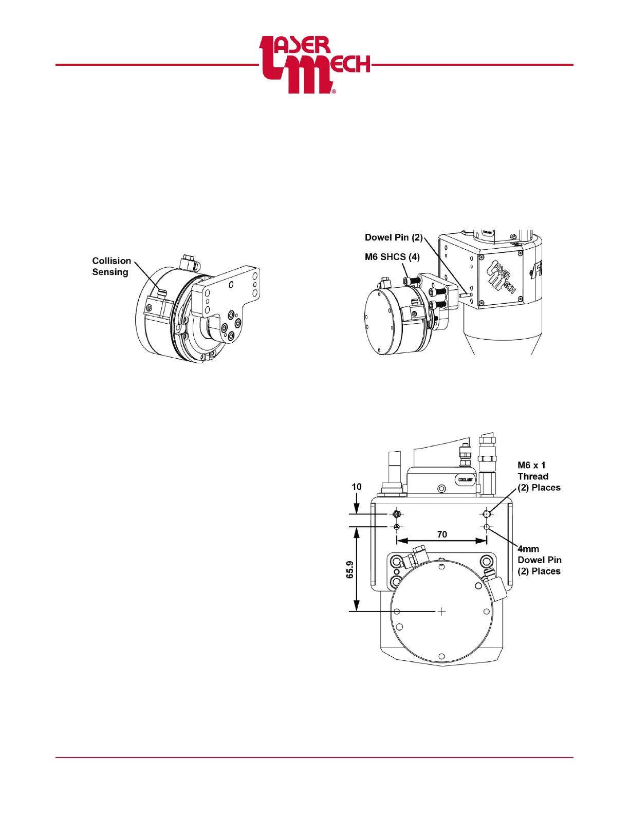
2.2 Mounting the Cutting Head to the
Robot Mount Bracket
The standard bracket holds the head in a
vertical orientation. The bracket bolts onto
the head using four M6 SHCS and is
positioned on two dowel pins (see Figure
4).
Figure 4
There is also a mount pattern on the back
side of the head to mount cable
management blocks to the robotic cutting
head. See Figure 5 for mounting pattern.
Figure 5