PLMNL0199 REV. J Effective Date: 08/05/21 19 FiberCUT
®
ST Operation Manual
Selecting a value of 00 allows you to
configure the Node Address up to 126
using Fieldbus Settings on the
Preferences page of FiberCUT
®
Monitor. See Section 5.6.
There is a termination resistor fitted on
the Interconnect Board. The resistor is
controlled using switch S5. See
Figure 22.
If this device is the last node in the
system, then S5 should be ON.
If this device is not the last node in
the system, then S5 should be
OFF.
There is also a termination switch
located on the 9-pin connector of the
Profibus cable.
The FiberCUT
®
controller ships
with this switch in the OFF
position.
This switch is redundant with the
previously mentioned S5 (see
PLCSA0017 Configuration
earlier in this section), so it can
remain OFF.
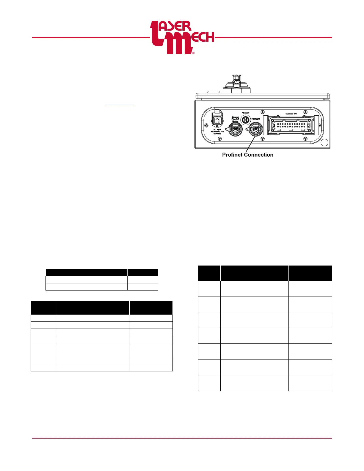
3.9.4 PROFINET
The connection to PROFINET uses an
RJ45 jack located in the FiberCUT
®
controller. Do not confuse the
PROFINET jack with the computer
Ethernet interface used for FiberCUT
®
Monitor. See Figure 23.
Figure 23
The FiberCUT
®
controller consists of a
HMS Industrial Networks Anybus IC
PRT module and Interconnect Board.
The customer must configure the
PROFINET Master to recognize this
slave device and map the data
correctly. Consult your system
manufacturer for specific instructions
on how to configure slave devices.
Object Name: Anybus-IC PRT / RT
Standard
Default Device Name: ABIC-PRT