PLMNL0199 REV. J Effective Date: 08/05/21 32 FiberCUT
®
ST Operation Manual
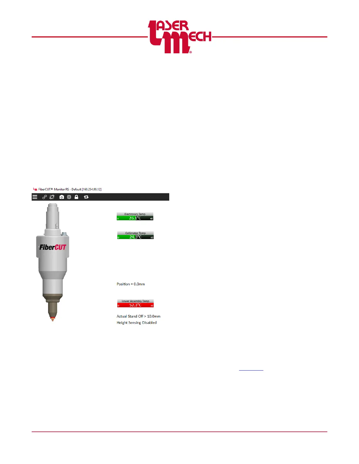
5.4.2 Displays
After FiberCUT
®
Monitor is connected
a series of meters appears. See
Figure 34.
Each meter displays the upper and
lower limits in small digits, along with
the current value and a scale
representing the current value.
If the sensor is within the normal
operating range, the scale is
displayed in green.
If the sensor is in a faulted state,
the scale is displayed in red. See
Figure 36.
Figure 36
Sensors include:
A thermometer for the primary
electronics.
A thermometer for the collimating
lens.
A thermometer for the lower
assembly, including the focusing
lens and cover glass.
These temperature readings are
valuable information that can indicate
problems with contaminated or
damaged optics, or poorly aligned
fibers.
The Position Display indicates the
physical position of the head within its
travel. The retracted position is zero
with the negative direction toward the
extended limit.
The Active Standoff Display indicates
the measured standoff distance as
determined by the capacitive height
sensor.
Readings above 10mm are
indicated as >10.0mm.
When the head is not actively
tracking a surface (no standoff is
selected) the message Height
Sensing Disabled is displayed.
Otherwise, the selected standoff
height is displayed.
5.4.3 Status and Fault Code History
The upper section of the Status panel
displays the current status of the
head, inputs and outputs. See Figure
37.
Inputs and outputs are displayed in:
Black when off.
Green when a true input or output
is active.
Orange when a simulated input is
active.
If Simulated Inputs is enabled in
Settings, clicking on the input will
toggle the simulated input on and off.
See Section 3 for a detailed
description of input and output signals.