47
ECP5 and ECP5-5G High-Speed I/O Interface
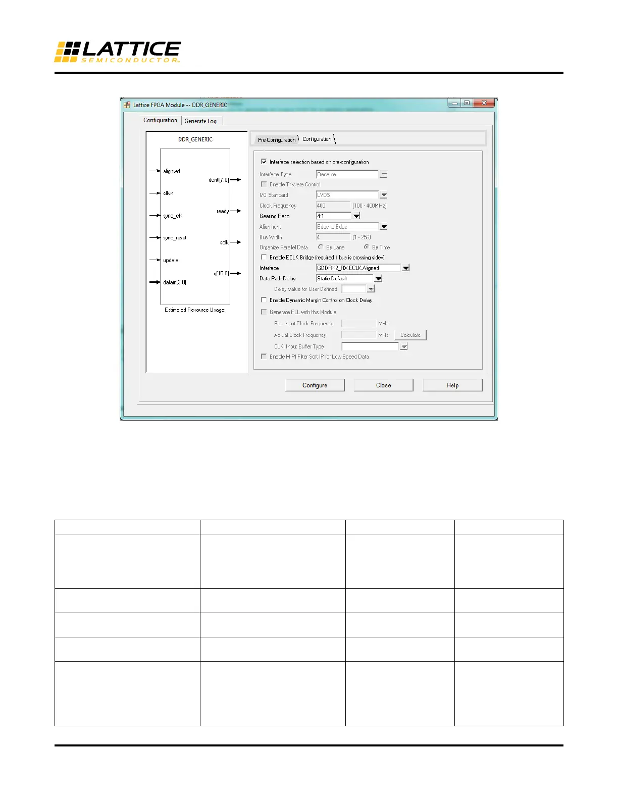
Figure 43. DDR_Generic Configuration Tab
The check box on the top of this tab indicates that the interface is selected based on entries in the Pre-Configura-
tion Tab. The user can choose to change these values by disabling this entry. The best suitable interface is picked
based on the selections made in the Pre-Configuration tab.
Table 8 explains the various parameters in the Configuration Tab
Table 8. DDR_Generic Configuration Tab Parameters
GUI Option Description Values Default Value
Interface selection based on pre-
configuration
Indicates interface is selected
based on selection made in the
Pre-configuration tab. Disabling
this checkbox would allow users to
make changes if needed.
ENABLED, DISABLED ENABLED
Interface Type Type of interface (Receive or Trans-
mit)
Transmit, Receive,
Receive MIPI
Receive
Enable Tristate Control Generate Tristate control for Trans-
mit Interfaces
ENABLED, DISABLED DISABLED
I/O Standard I/O Standard used for the interface All Legal Input & Output
standards
LVC MO S 25
Clock Frequency Speed of the Interface 100 MHz – 400 MHz
(Transmit)
3.125 MHz – 400 MHz
(Receive)
200 MHz – 400 MHz
(Receive MIPI)
200 MHz
 Loading...


