3.2 Setup of the device
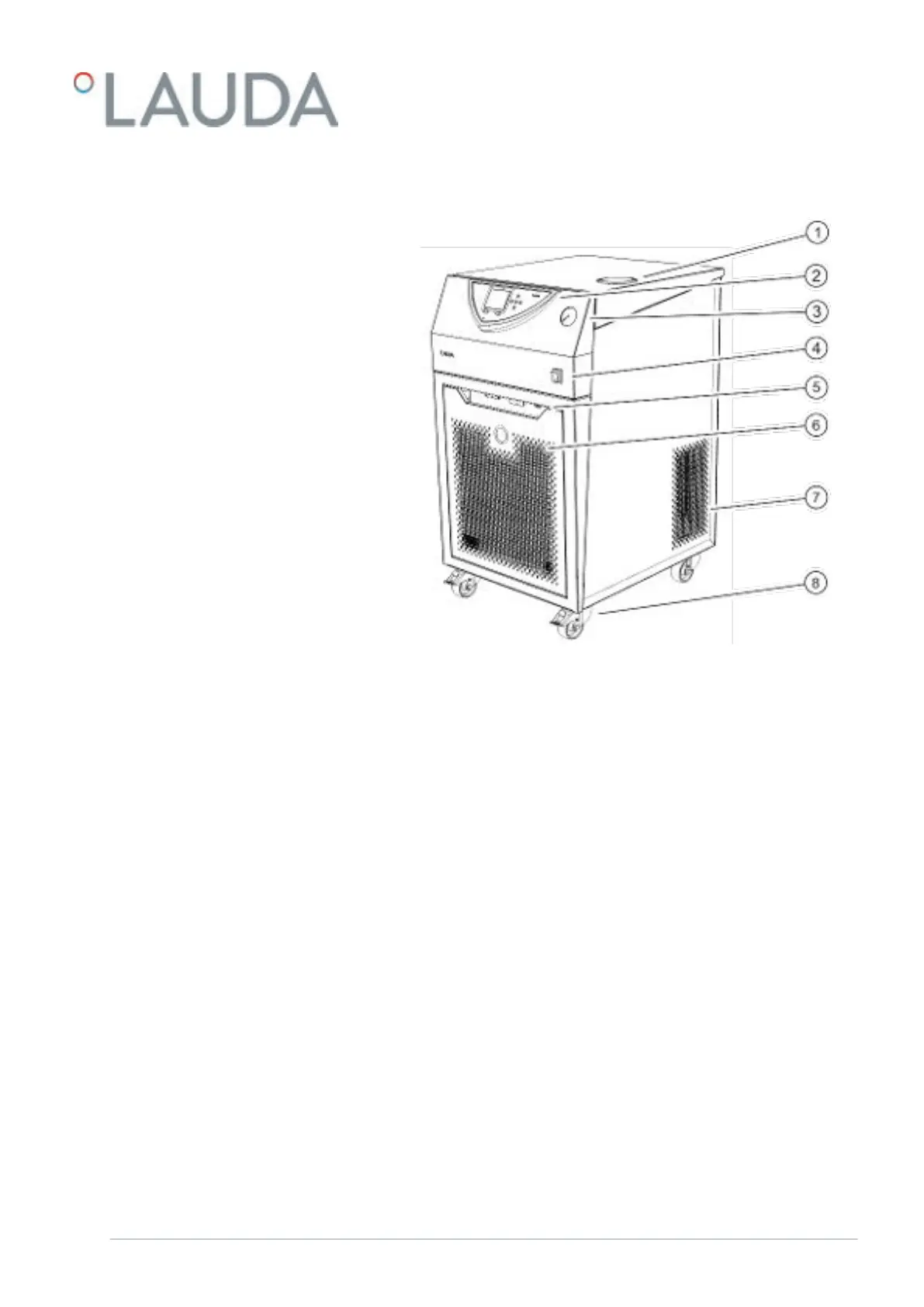
Fig. 1: Front of the VC 3000
1 Filler nozzle with cover
2 Control panel
3 Pressure gauge
4 Mains switch
5 Alarm output and module bays
6 Front panel (ventilation openings only in case of air-cooled devices)
7 Ventilation openings (on both sides)
8 Four castors (front castors with locking brake)
V08 Variocool 15 / 97