About X-431 Station
Diagnostics
Toolbox & Apps
FAQ
Initial Use
98
www.x431.com +86 755 8455 7891
LAUNCH
Station
User's Guide
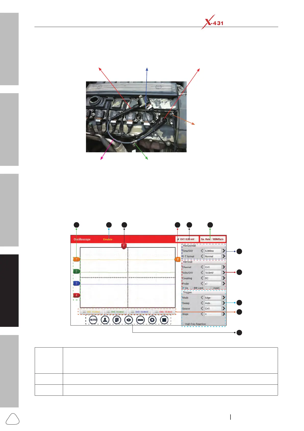
crocodile clips to ground.
The connection is as follows:
COP earth
cord &
crocodile clips
to ground
Ignition coil
COP earth cord
COP extension
cord
The high-voltage clips to
the insulated lead of the
COP extension cord
Spark plug
Connection Method 3 (While testing Secondary-direct ignition analysis)
For detailed operations, please refer to Chapter 7.4.
3). Screen Layout
Below displays the initial interface of the Scopebox.
1 32 54 6
7
8
9
10
11
Fig. Oscilloscope-1
1
Displays the CH1/CH2/CH3/CH4 information:
Readout shows the coupling and vertical scale factors of the channels.
A “B” icon indicates that the channel is bandwidth limited.
2 Working mode
3 Horizontal trigger position marker