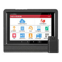
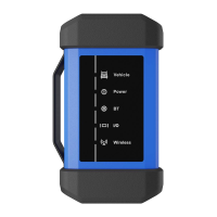
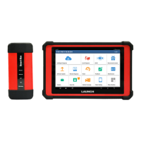
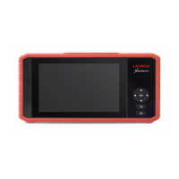
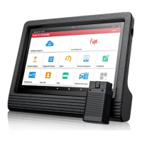
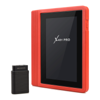
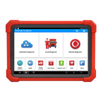
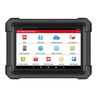
About X-431 Station
Diagnostics
Toolbox & Apps
FAQ
Initial Use
106
www.x431.com +86 755 8455 7891
LAUNCH
Station
User's Guide
4.4 Ignition (Optional)
The ignition system is the system which has greatest impact on the performances of gasoline engine, as
the statistical data shows that nearly half of the failures are caused by poor work of electrical system. And
the performance tests of engine often start from the ignition system. Nowadays ignition system includes
distributor and distributorless. Distributorless includes independent ignition and simultaneous ignition.
1. Distributor ignition system i.e. contact breaker with contact-controlled ignition system (commonly known
as the platinum) and contact breaker with noncontact-controlled ignition system combined with magnet,
hall components or infrared.
2. Independent ignition system: crankshaft sensor send out the ignition timing signal and cylinder
identification signal so that the ignition system can send out ignition signal to specified cylinder in
specied time, each cylinder has its independent ignition coil.
3. Simultaneous ignition system: two cylinders share one ignition coil, when two cylinder pistons reach top
dead center at the same time (one is compression, another is the exhaust), two spark plugs will be ignited
at the same time, at this time, the ignition for the former cylinder is in high-pressure low temperature gas
mixture, the ignition is valid, while for the latter one is in low-pressure high temperature exhaust gas, the
ignition is invalid.
X-431 Station can test and analyze the secondary signal for various engine ignition systems.
The Ignition module utilizes the same hardware device as the Scope module.
4.4.1 Secondary-distributor ignition analysis
The following connection should be made before performing it:
1. Power the Scopebox on: Power is provided to the Scopebox in either of the following ways:
• Power adapter: Insert one end of the power adapter into the Power interface of the Scopebox, and the
other end to the AC outlet.
• Battery clamps cable: Plug one end of the power adapter into the Power interface of the Scopebox,
and then clamp the other two terminals to the vehicle's battery (Red to +, and Black to -) respectively.
2. Connect the B-shaped terminal of the data cable to the Scopebox Data I/O port, and the other end to the
Data I/O port of the USB hub.
3. Plug the BNC end of secondary ignition pickup into CH1/CH2/CH3/CH4 channel of the Scopebox, and
connect the high-voltage clip to high-voltage line, and crocodile clips to ground.
*Tips: Common ignition sequence (the specific sequence is subject to the actual engine ignition sequence)
Four-stroke in-line four-cylinder: 1-2-4-3, or 1-3-4-2
Four-stroke in-line six-cylinder: 1-5-3-6-2-4, or 1-4-2-6-3-5
Four-stroke in-line eight-cylinder: 1-8-4-3-6-5-7-2
Five-cylinder: 1-2-4-5-3
V 6 engine: generally speaking, based on the person sitting on the driver cab, if the right side cylinder numbers on
the right side, from the front to the back are as follows: 1, 3, 5; and the cylinder numbers on the left side, from the
front to the back are as follows: 2, 4, 6; then the ignition sequence is: 1-4-5-2-3-6. If the cylinder numbers on the right
side, from the front to the back are as follows: 2, 4, 6; and cylinder numbers on the left side, from the front to the back
are as follows: 1, 3, 5; then the ignition sequence is: 1-6-5-4-3-2.
Fig. Ignition-1 below shows the normal ignition waveform of distributor ignition system, the upper one is the
secondary waveform, and the lower one is the primary waveform.
The secondary waveform
A section is contact open period; B section is make contact period, which is the magnetizing eld of ignition
coil.
 Loading...
