About X-431 Station
DiagnosticsToolbox & AppsFAQ
Initial Use
111
www.x431.com +86 755 8455 7891
LAUNCH
Station
User's Guide
Fig. Ignition-6
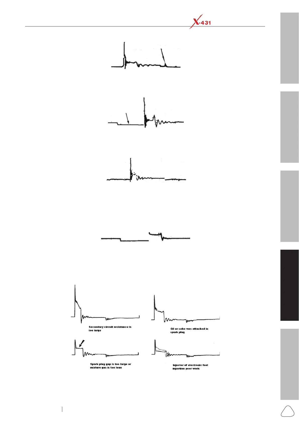
The curve on Fig. Ignition-7 shows the contact angle is too small during the magnetizing period, which is
caused by too large contact gap.
Fig. Ignition-7
A lot of clutter will be displayed on the horizontal section of primary waveform if contact has poor grounding,
as shown below Fig. Ignition-8.
Fig. Ignition-8
Fig. Ignition-9 shows the fault of low-voltage waveform in electronic ignition system. The voltage does not
rise during magnetizing, which indicates that the effect of limitation of the circuit failed and no components
on distributorless ignition system can be adjusted. When this waveform is abnormal, you can only replace
the ignition coils, igniter, ignition signal generator and cam position sensor, etc., one by one, to nd out the
faulty component or module.
Fig. Ignition-9
The secondary waveform is also affected by the spark plug, the combustion process, mixture gas
composition, the engine thermal state of the ignition coil, etc., which is more complicated. The following
lists a large number of measured secondary faulty waveform for reference. Since various factors lead to the
failures, Fig. Ignition-10 just shows the major possible factors for the failures.