ELECTRICAL SYSTEM OPERATION UNITY MOTORHOME
92
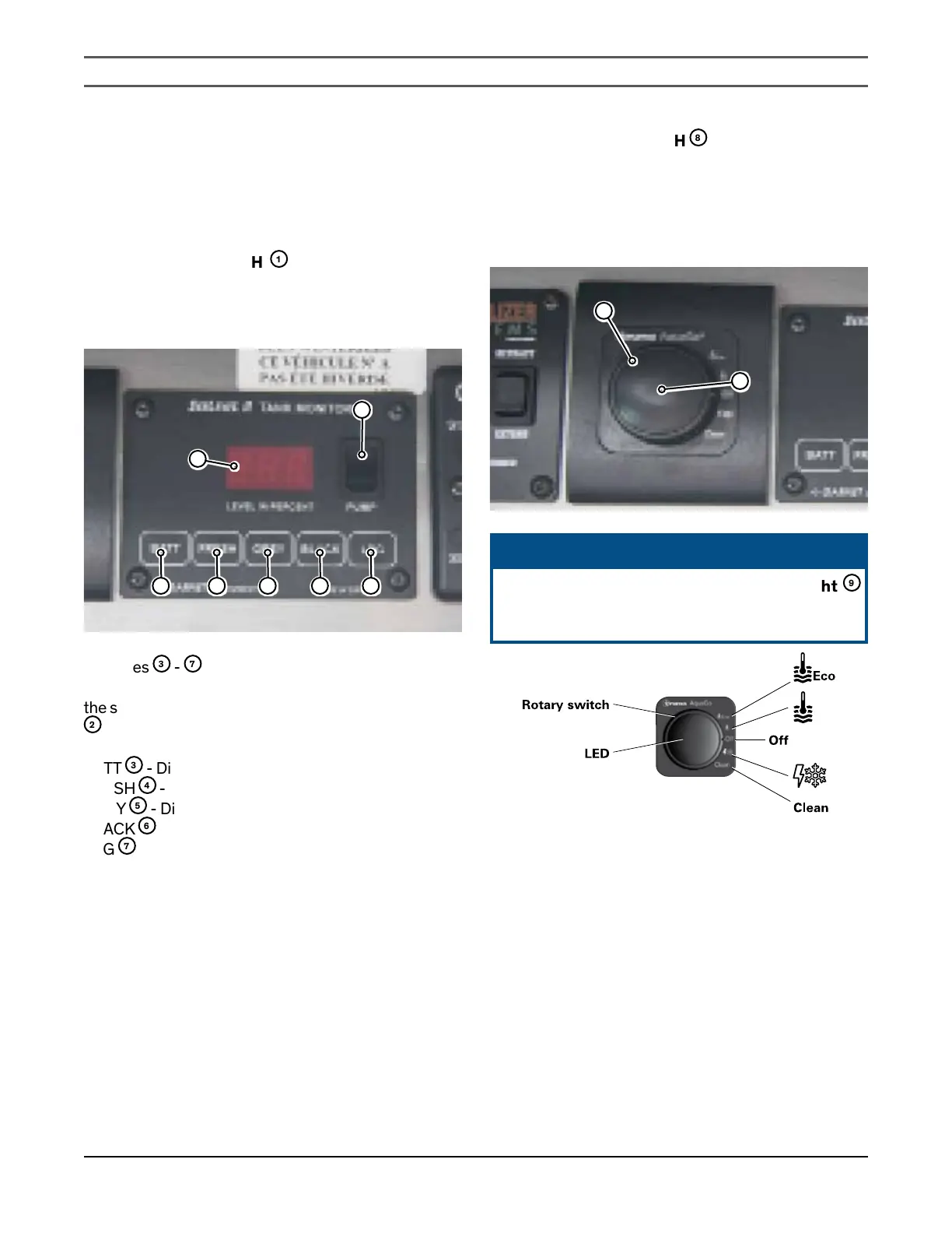
SYSTEM MONITOR
The system monitor panel, located in the cabinet above
the coach entrance doorway, monitors the following
systems:
WATER PUMP SWITCH
1
This switch controls the power to the water pump. The
light above the switch illuminates when the water pump
is activated.
1
2
3 4 5 6 7
Switches
3
-
7
Depress the following switches to monitor the level of
the system capacity used/available on the LED display
2
:
BATT
3
- Displays the coach battery power level
FRESH
4
- Displays the fresh water holding tank level
GREY
5
- Displays the grey water holding tank level
BLACK
6
- Displays the black water holding tank level
LPG
7
- Displays the LP Gas tank level
Refer to the detailed operating instructions in the
Motorhome Information Kit
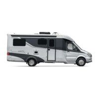
WATER HEATER SWITCH
8
This switch controls the power to the water heater. Turn
the switch counterclockwise from the “OFF” position
for water heater function or clockwise from the “OFF”
position for winterization or cleaning. Reverse direction
to the “OFF” position to turn off the water heater.
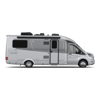
8
9
ᘐ NOTICE
The on-demand water heater switch light
9
illuminates when the water heater is turned to
the ON setting.