MOTORHOME OPERATION UNITY MOTORHOME
52
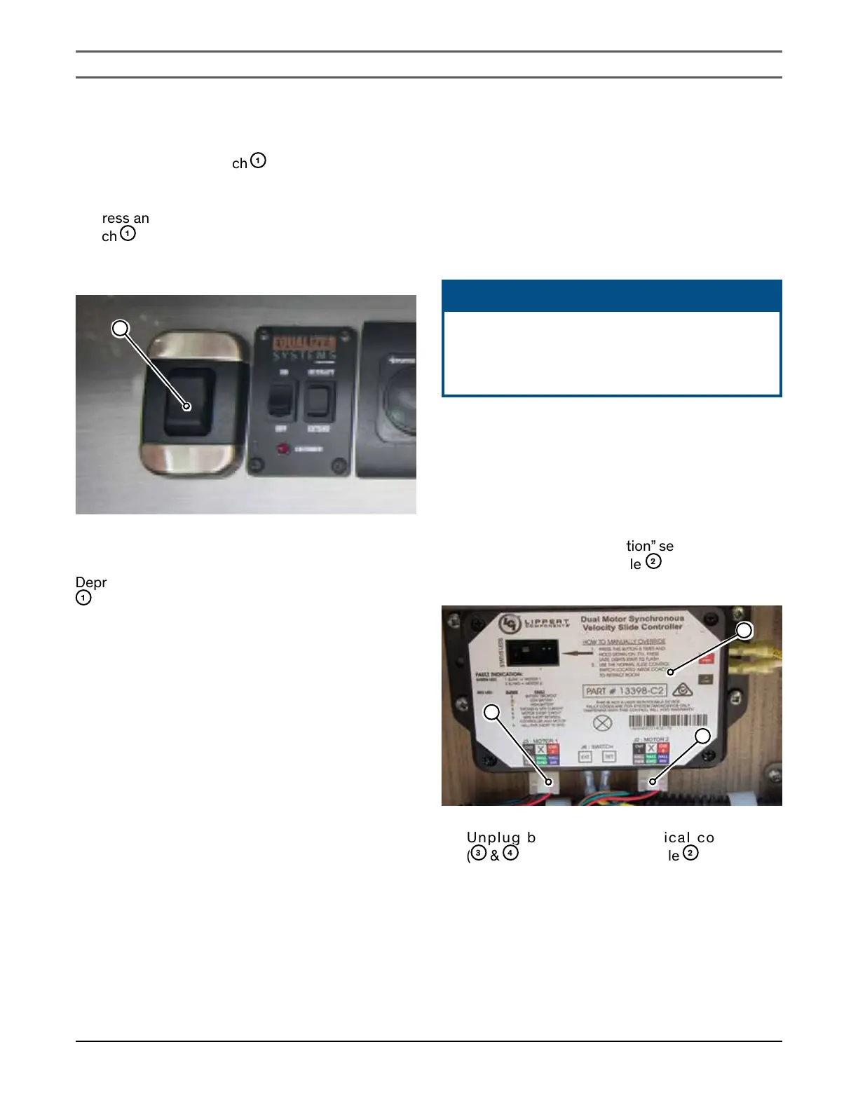
EXTENDING THE SLIDE OUT ROOM
The slide out control switch
1
is located in the cabinet
above the coach entrance doorway.
Depress and hold the bottom of the slide out control
switch
1
until the slide out room is fully extended,then
release the switch. Fully extend the slide out room to
ensure the all-weather seals are in correct alignment.
1
RETRACTING THE SLIDE OUT ROOM
Depress and hold the top of the slide out control switch
1
until the slide out room is fully retracted, then release
the switch. Fully retract the slide out room to ensure the
all-weather seals are in correct alignment.
SERVICING ALLWEATHER SEALS
Cracked or worn all-weather seals around the slide
out room may allow dirt and moisture to enter your
motorhome which could lead to premature interior wear.
Inspect the all-weather seals in the spring and fall, and
have them replaced if necessary.
Extensive travel and use in severe weather conditions may
cause more rapid deterioration of some components,
especially all-weather seals.
Have professional service personnel, adjust, maintain
and replace the all-weather seals to extend the life and
comfort of your slide out room.
SLIDE OUT ROOM EMERGENCY
OPERATION
If the slide out room fails to extend or retract electrically,
you can manually operate the slide out mechanism.
Manual operation of the slide out is not recommended
unless the slide out needs to be retracted in order to
move the motorhome.
ᘐ NOTICE
The slide out electrical function is protected by
a fuse located on the power distribution panel.
Check that the fuse is intact before resorting to
manual slide out operation.
ACCESSING THE MOTOR MOUNTING SCREW
WHEN SLIDE OUT IS IN U24CB AND U24FX
1.
Turn the battery disconnect switch to the “OFF”
position, and disconnect the shore power. Refer
to the “Battery Disconnect Switch” section in the
“Electrical System Operation” section.
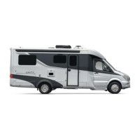
2.
Locate the control module
2
(installed in lower
galley.)
2
3
4
3.
Unplug both motor electrical connectors
(
3
&
4
) from the control module
2
.