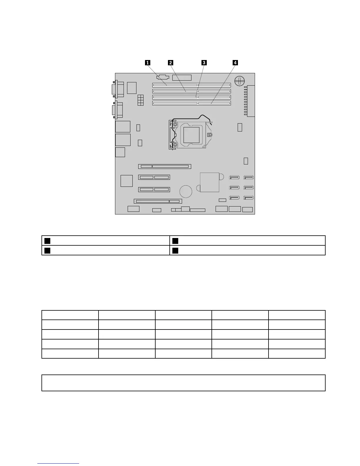
Thefollowingillustrationhelpsyoutolocatethememoryslotsonthesystemboard.
Figure42.Memoryslotsonthesystemboard
1Memoryslot4(DIMMB2)3Memoryslot2(DIMMA2)
2Memoryslot3(DIMMB1)4Memoryslot1(DIMMA1)
Thefollowingtableprovidesinformationaboutthememorymoduleinstallationrulesthatyoushould
considerwheninstallingorremovingamemorymodule.The“X”markindicatesthememoryslot(s)into
whichthememorymodule(s)shouldbeinstalledindifferentsituations.Thenumbers1,2,3,and4indicate
theinstallationsequence.
Note:Theinstalledmemorymodulesmustbethesametypewiththesamevoltageandfrequency.
UDIMMDIMMA1DIMMA2DIMMB1DIMMB2
OneUDIMM
X
TwoUDIMMsX,1X,2
ThreeUDIMMsX,3X,1X,2
FourUDIMMsX,3X,1X,4X,2
Installingamemorymodule
Attention:Donotopenyourserverorattemptanyrepairbeforereadingandunderstandingthe“Safetyinformation”
onpageiii
and“Guidelines”onpage85.
Thistopicprovidesinstructionsonhowtoinstallamemorymodule.
Beforeyoubegin,printalltherelatedinstructionsorensurethatyoucanviewthePDFversiononanother
computerforreference.
Chapter6.Installing,removing,orreplacinghardware95