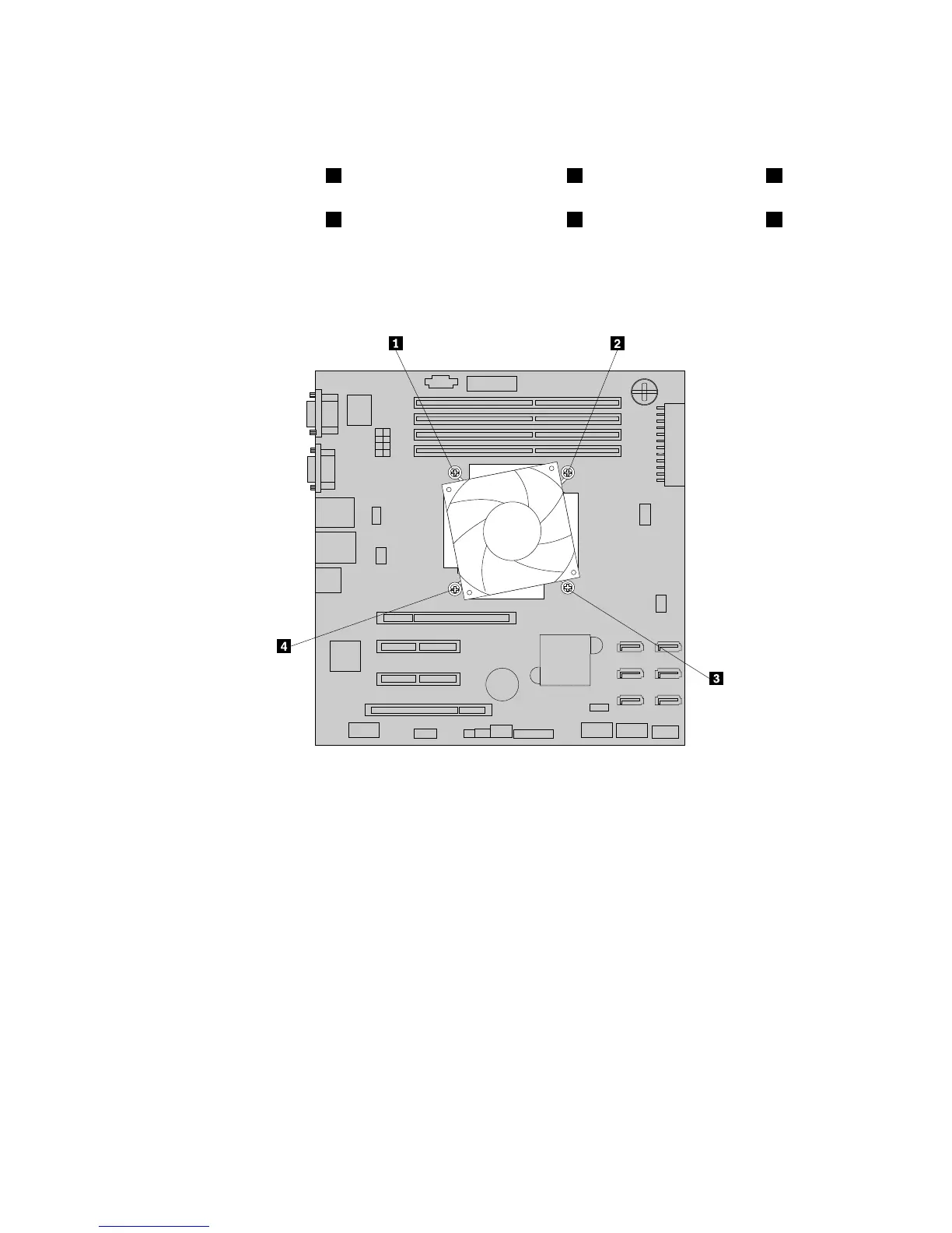
6.Removethefourscrewsthatsecuretheheatsinkandfanassemblytothesystemboard.Itis
recommendedthatyoucarefullyremovethefourscrewsfromthesystemboardusingthefollowing
methodtoavoidanypossibledamagetothesystemboard.
a.Partiallyremovescrew1,thencompletelyremovescrew3,andthenreturntoscrew1and
completelyremoveit.
b.Partiallyremovescrew2,thencompletelyremovescrew4,andthenreturntoscrew2and
completelyremoveit.
Note:Thefourscrewsareintegratedpartsoftheheatsinkandfanassembly.Donottrytoremovethe
fourscrewsfromtheheatsinkandfanassembly.
Figure98.Removingthescrewsthatsecuretheheatsinkandfanassembly
7.Gentlytwisttheheatsinkandfanassemblytofreeitfromthemicroprocessorandthenlifttheheatsink
andfanassemblyoffthesystemboard.
8.Layasidetheoldheatsinkandfanassembly.Touchthestatic-protectivepackagethatcontainsthenew
heatsinkandfanassemblytoanyunpaintedsurfaceontheoutsideoftheserver.Then,removethenew
heatsinkandfanassemblyfromthepackage.
Notes:
•Whenhandlingtheheatsinkandfanassembly,donottouchthethermalgreaseonthebottomofit.
•Beforeinstallingthenewheatsinkandfanassembly,besuretousethecleaningpadthatcomeswith
thenewheatsinkandfanassemblytowipethethermalgreasefromthetopofthemicroprocessor.
Disposeofthecleaningpadafterallofthethermalgreaseisremovedfromthemicroprocessor.
9.Placethenewheatsinkandfanassemblyonthesystemboardsothatthefourscrewsonthenewheat
sinkandfanassemblyarealignedwiththecorrespondingmountingstudsonthesystemboard.Note
theorientationofthenewheatsinkandfanassemblyandmakesurethatyouproperlyplaceitsothat
youcaneasilyconnecttheheatsinkandfanassemblycabletothemicroprocessorfanconnectoron
thesystemboard.See“Systemboardcomponents”onpage45
.
Chapter6.Installing,removing,orreplacinghardware165