b. Remove both PCIe riser cages or fillers, the chassis air baffle, and the PCIe expansion tray (see
“Remove a 4U PCIe riser cage” on page 255, “Remove the chassis air baffle” on page 270, and
“Remove the 4U PCIe expansion tray” on page 249).
c. Remove the system board air baffle (see
“Remove the system board air baffle” on page 226) or
the processor and memory expansion tray and the expansion tray air baffle (see
“Remove the
processor and memory expansion tray” on page 219
).
d. Remove the fan cage assembly (see
“Remove the fan cage assembly” on page 153).
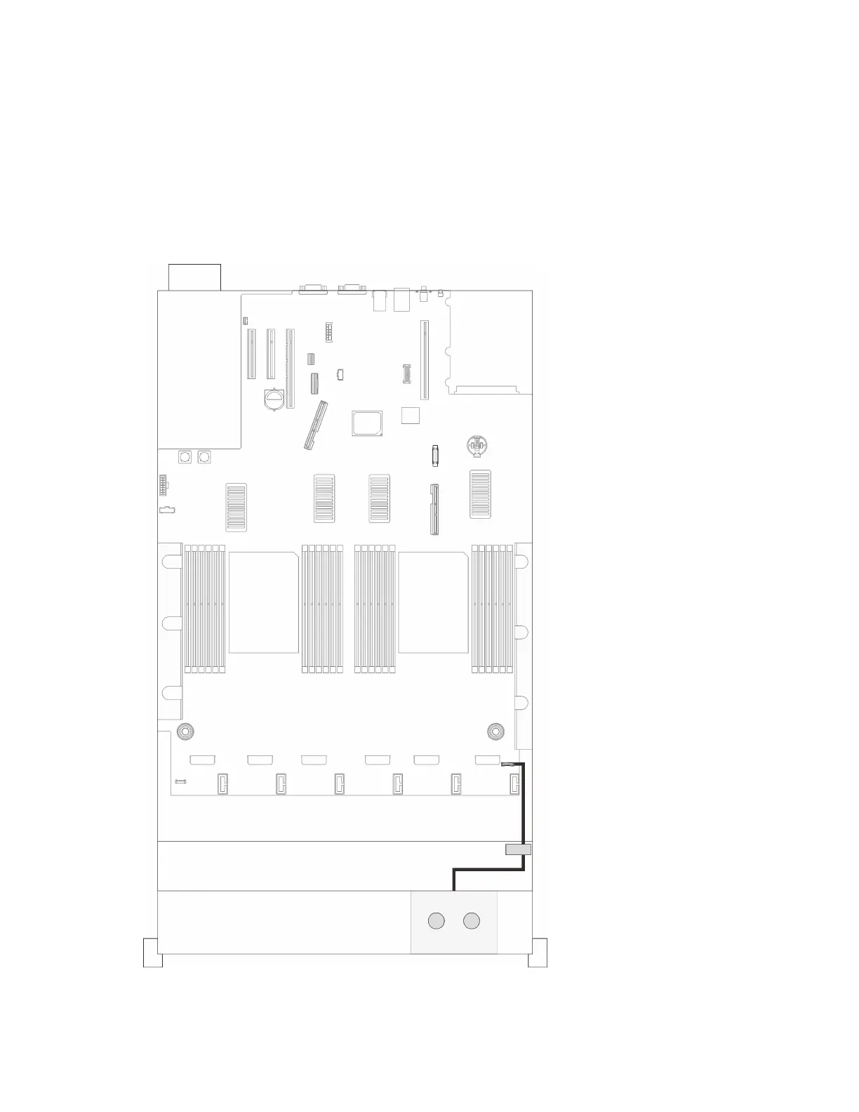
Step 2. Disconnect the LCD diagnostics panel cable.
Figure 64. Disconnecting the LCD diagnostics panel cable
174 ThinkSystem SR860 V2 Maintenance Manual

 Loading...


