7 Drive application
7.1 Parameterisation dialog
124
Lenze · 8400 BaseLine C · Reference manual · DMS 1.6 EN · 01/2014 · TD05
_ _ _ _ _ _ _ _ _ _ _ _ _ _ _ _ _ _ _ _ _ _ _ _ _ _ _ _ _ _ _ _ _ _ _ _ _ _ _ _ _ _ _ _ _ _ _ _ _ _ _ _ _ _ _ _ _ _ _ _ _ _ _ _
7.1.1 Signal flow
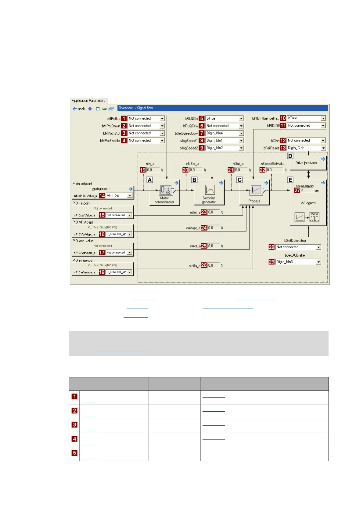
When you go to the Application parameters tab to the top dialog level Overview and click the Signal
flow button, you will get one dialog level down to the signal flow of the application (here displayed
with the preset control mode "Terminals 0"):
Configuration parameters for digital control signals:
Motor potentiometer (L_MPot_1) Device control (LS_DriveInterface)
Setpoint generator (L_NSet_1
) Motor control (MCTRL)
Process controller (L_PCTRL_1)
All input and output interfaces of the application are described in the chapter entitled
"Interface description
". ( 127)
Parameter
Selection of signal source
(Lenze setting)
for control signal:
bMPotUp
(C701/8)
0: Not connected L_MPot_1: Increase speed setpoint
bMPotDown
(C701/9)
0: Not connected L_MPot_1: Decrease speed setpoint
bMPotInAct
(C701/10)
0: Not connected L_MPot_1: Activate inactive function
bMPotEnable
(C701/11)
0: Not connected L_MPot_1: Activate motor potentiometer function
bRLQCw
(C701/17)
1: C_bTrue Activate clockwise rotation (fail-safe)