5 Motor control (MCTRL)
5.4 V/f characteristic control (VFCplus)
80
Lenze · 8400 BaseLine C · Reference manual · DMS 1.6 EN · 01/2014 · TD05
_ _ _ _ _ _ _ _ _ _ _ _ _ _ _ _ _ _ _ _ _ _ _ _ _ _ _ _ _ _ _ _ _ _ _ _ _ _ _ _ _ _ _ _ _ _ _ _ _ _ _ _ _ _ _ _ _ _ _ _ _ _ _ _
5.4.2 Basic settings
The "Initial commissioning steps" listed in the table below are sufficient for a simple characteristic
control.
• Detailed information on the individual steps can be found in the following subchapters.
Tip!
Information on the optimisation of the control mode and the adaptation to the real appli-
cation is provided in the "Optimise control behaviour
" chapter. ( 82)
Parameterisable additional functions are described correspondingly in the
"Parameterisable additional functions
" chapter. ( 92)
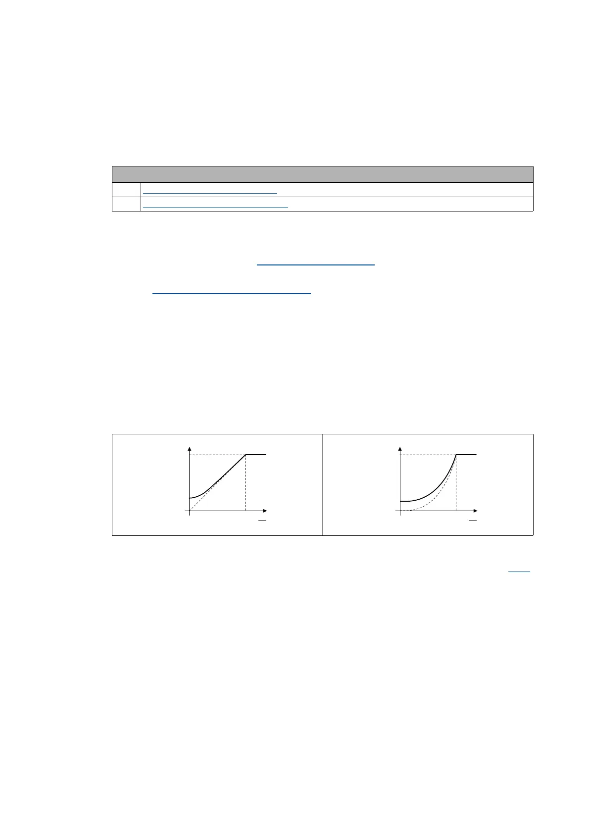
5.4.2.1 Defining the V/f characteristic shape
Generally, two different characteristic shapes can be defined:
1. Linear V/f characteristic:
For drives for a constant, speed-independent load torque.
2. Quadratic V/f characteristic:
For drives with a load torque curve which is quadratic or in relation to speed. Quadratic V/f cha-
racteristics are preferred in the case of centrifugal pumps and fan drives.
[5-2] Principle of a linear and quadratic V/f characteristic
The V/f characteristic shape is defined by selecting the corresponding motor control mode in C006:
• "6: VFCplus: V/f linear" for linear characteristic
• "8: VFCplus: V/f quadr" for square-law characteristic
Initial commissioning steps
1. Defining the V/f characteristic shape
. ( 80)
2. Defining current limits (Imax controller)
. ( 81)