Function block library
7-76
SHB9300CRV EN 2.0
7.6.17.1 Evaluation of the contouring error
The actual contouring error signal is generated by thefunction block CCTRL (output CCTRL-POUT)
and read at CERR1-PHI-IN (see e.g. signal-flow chart configuration 1000).
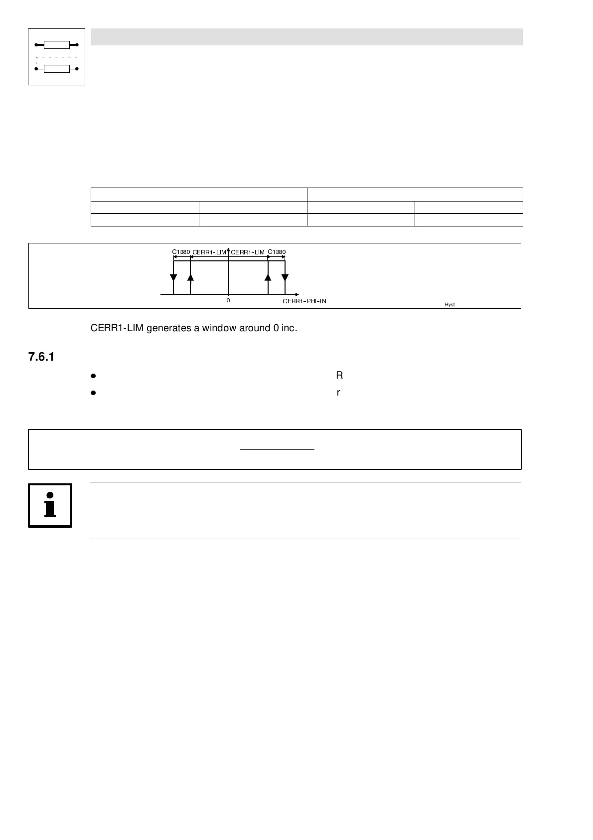
Inthefunction block,it is compared to the configurable contouring errorlimit CERR1-LIM. If the limit
is exceeded, the contouring error warning is available at the output CERR1-ERR:
Input signal Output signal
CERR1-PHI-IN Within the window CERR1- ERR LOW
Outside the window HIGH
&(553+,,1
&
&(55/,0&(55/,0
&
Hyst
CERR1-LIM generates a window around 0 inc.
7.6.17.2 Determination of the contouring error limits
l
The contouring error limit is selected at the input CERR1-LIM.
l
The limit for the contouring error pre-warning is determined through the reduction value
CERR1-WFAC.
– Limit value calculation of the contouring error pre-warning:
|
CERR1-LIM
|
ô
|
CERR1-WFAC
|
100 %
Note!
The input values at CERR1-LIM are limited to a maximum of 4194300 inc (4194300 inc = 63.9
revolutions).