Function block library
7-223
SHB9300CRV EN 2.0
T
SYNC
CANNEL 1
SYNC
-
SIGNA
[1 0 V ; 1 m s ]
GND1
CANNEL 2
SYNC1-IN3
[x ,x % ; 1 m s ]
CANNEL
3
SYNC1-O UT3
[x ,x % ; 1 m s ]
GND2
GND3
T
IN T P O L
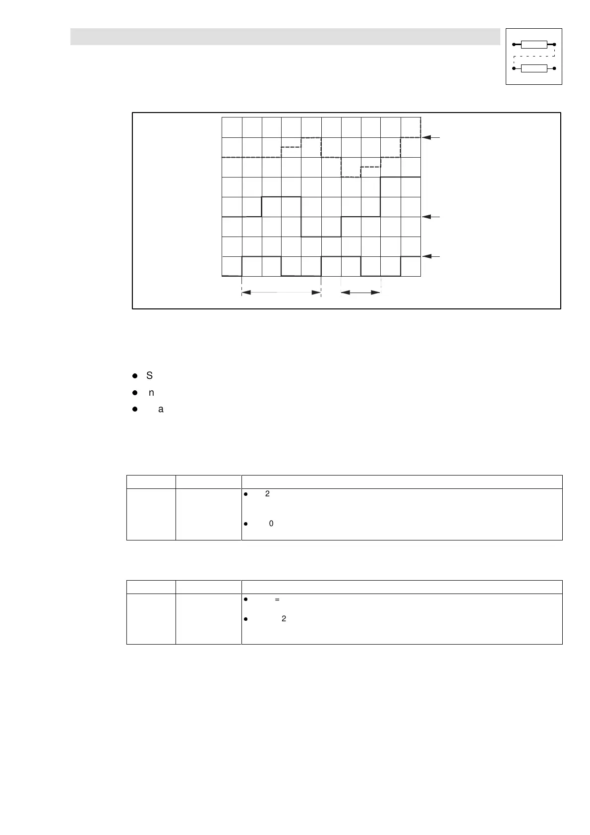
Fig. 7-182 Example of an interpolation
See Fig. 7-182:
An analog value at SYNC1-IN3 is output as an interpolated value SYNC1-OUT3.
l
Sync cycle (C1121/1) = 4 ms
l
Interpolation cycle (C1121/2) = process cycle = 2 ms
l
Phase shift (C1123/1) = 0 ms
7.6.74.3 Phase shift
Phase shift for the synchronization via system bus (SYNC TIME)
Code Value Function
C1122 0 ...10.000 µs
l
C1120 = 1
– Phase shift between the sync telegram and the start of the internal control program.
– The parameters are set automatically depending on the parameterization of the system bus (CAN).
l
C1120 = 2
– C1122 has no effect
Phase shift for the synchronization via terminal (PHASE SHIFT)
Code Value Function
C1123/1 -1.000 ms
bis
+1.000 ms
l
C1120 = 1
– C1123/1 has no effect
l
C1120 = 2
– Phase shift between the sync signal and the start of the internal control program (e.g. to compensate
the effects of signal run times / dead times for the sync signal of the individual slaves).