Installation
4-10
SHB9300CRV EN 2.0
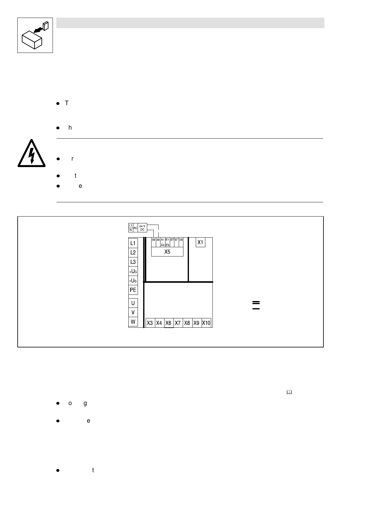
4.2.1.2 Insulation
The controllers have an insulation (isolating distance)between the power terminals and the control
terminals as well as to the housing:
l
Terminals X1 and X5 have a double basic isolation (double insulating distance, safe mains
isolation to VDE0160, EN50178). The protection against contact is ensured without any
further measures.
l
The control inputs and outputs of all controllers are electrically isolated.
Danger!
l
Terminals X3, X4, X6, X7, X8, X9, X10 have a single basic isolation (single insulating
distance).
l
Protection against contact in the event of fault is ensured only by additional measures.
l
If an external voltage supply (24V DC) is used, the insulation level of the controller depends
on the insulation level of the voltage source.
reinforced insulation
single basic insulation
Fig. 4-6 Basic insulation in the controller
4.2.1.3 Replacement of defective fuses
Replace defective fuses with the prescribed type only when no voltage is applied. (
&
3-6)
l
For single drives, the controller carries a hazardous voltage up to three minutes after mains
disconnection.
l
In a drive network, all controllers must be inhibited and disconnected from the mains.
4.2.1.4 Mains disconnection
Make a safety disconnection between the controller and the mains only via a contactor at the input
side.
l
Please note that in a drive network all controllers must be inhibited.