Installation
4-18
SHB9300CRV EN 2.0
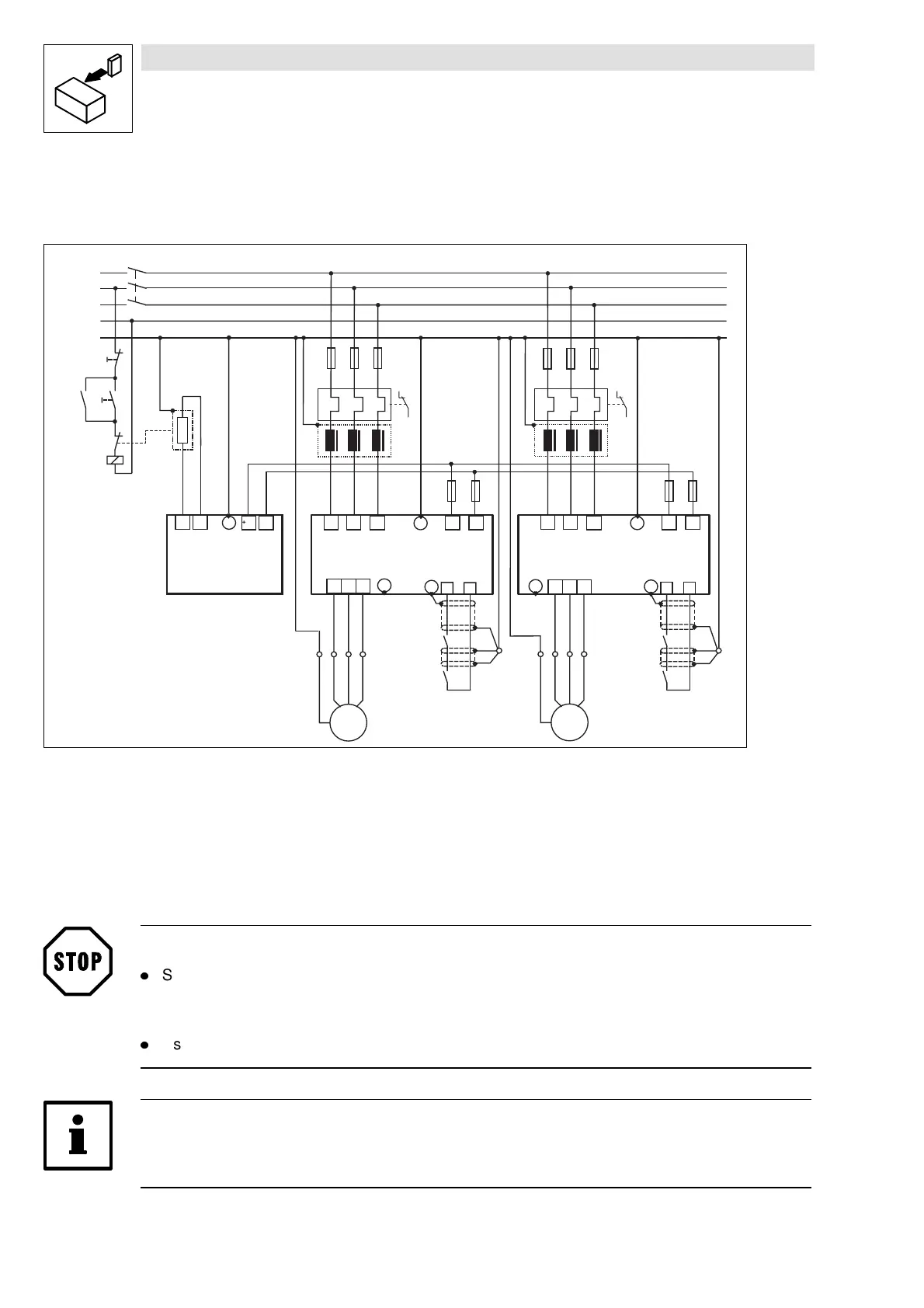
4.2.7.4 DC bus connection of several drives
Decentralized supply with brake module
K1
K1
L3
N
PE
L1
L2
U
V
W
M
3~
PE
L1 L2 L3
F1
932X - 933X
PE
+U G -U G
PE
RB
ϑ
+U G
-U G
9352
PE
RB2
RB1
Z1
X1
Z3
RB
K1
U
V
W
M
3~
PE
L1 L2 L3
932X - 933X
PE
+U G
-U G
PE
Z2
F7
F8
F9 F10
ON
OFF
28
A4
PE
28
A4
K1
RFR
PE
X2
K1
RFR
F2 F3
F4
F5 F6
Z4
Fig. 4-9 Decentralized supply with DC-bus connection of several drives
Z1, Z2 M ains filter (for selection see Manual, P art F)
Z3 Brake chopper
Z4 Brake resistor (for r.m.s. current monitoring see the Manual, P art F)
F1...F6 Fu s es ( s ee chap ter 3.3.4 an d c h apter 4.2.7 .1)
F7...F10 D C -b u s fu s e ( see ch apter 3.3.4 / 4.2.7.1 ); fus e holder with/without alarm contact
K1 M ain contactor
Stop!
l
Set the DC bus voltage thresholds of controller and brake unit to the same values.
– Controller using C0173
– Brake unit with switches S1 and S2
l
Use a bimetal relay to monitor the mains supply.
Note!
Observe the information given in Part F of the Manual and the application report “DC-bus
connection” to select the components.