Example for operang mode
Parameter Name Seng for this example
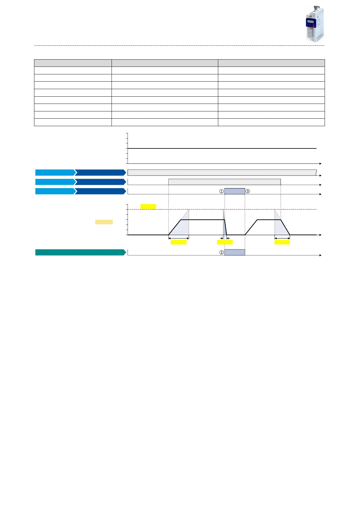
0x2631:001 (P400.01) Enable inverter Constant TRUE [1]
0x2631:002 (P400.02) Run Digital input 1 [11]
0x2631:003 (P400.03) Acvate quick stop Digital input 2 [12]
0x2838:003 (P203.03) Stop method Standard ramp [1]
0x2916 (P211.00) Maximum frequency 50 Hz
0x2917 (P220.00) Acceleraon me 1 4 s
0x2918 (P221.00) Deceleraon me 1 3 s
0x291C (P225.00) Quick stop deceleraon me 1 s
0 Hz
30 Hz
10 Hz
20 Hz
40 Hz
50 Hz
60 Hz
t
0 Hz
30 Hz
10 Hz
20 Hz
40 Hz
50 Hz
60 Hz
t
t
t
t
t
0x2916
0x2917 0x291C
0x2918
0x2DDD
Status signals
Quick stop active [54]
Digital input 2 [12] Activate quick stop
Digital input 1 [11] Run
Constant TRUE [1] Enable inverter
FunctionTrigger
Output signals
Output frequency
Input signals
Frequency setpoint selection
①
Quick stop is acvated: The motor is brought to a standsll within the deceleraon me set in 0x291C (P225.00).
②
If quick stop is acve, the status signal "Quick stop acve [54]" is set to TRUE. This status signal can be assigned via the Flexible I/O congu-
raon of a funcon or a digital output.
③
Quick stop is deacvated again: The motor accelerates again to the setpoint since the start command is sll acve.
Basic seng
Quick stop
110

 Loading...


