4.3 Control connecons
Terminal descripon Relay output Control terminals
Connecon X9 X3
Connecon type pluggable screw terminal Spring terminal
Min. cable cross-secon mm² 0.5 0.5
Min. cable cross-secon AWG 22 22
Max. cable cross-secon mm² 1.5 1.5
Max. cable cross-secon AWG 14 16
Stripping length mm 6 9
Stripping length inch 0.24 0.35
Tightening torque Nm 0.2 -
Tightening torque lb-in 1.8 -
Required tool 0.4 x 2.5 0.4 x 2.5
4.4 Networks
4.4.1 CANopen/Modbus RTU
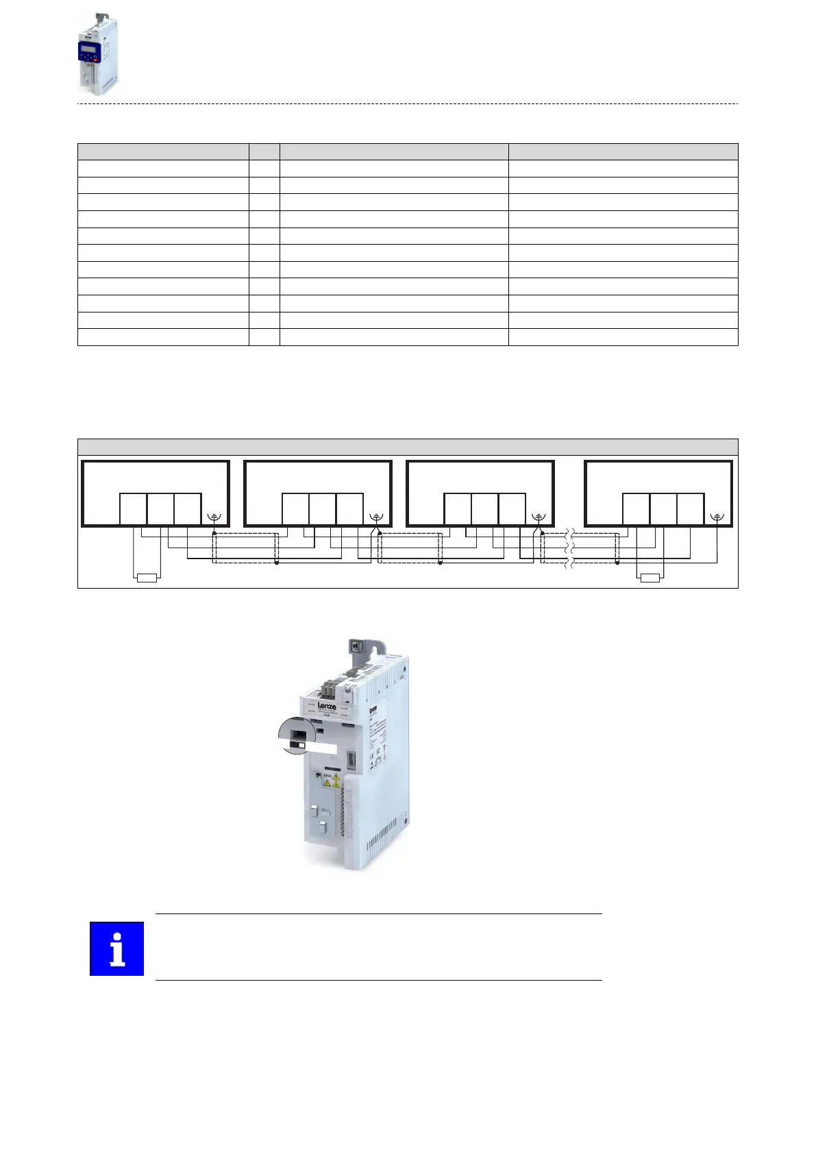
Typical topologies
Line
A1 A2 A3 An
X216 X216 X216 X216
120120
CG/
COM
CL/
TA
CH/
TB
CG/
COM
CL/
TA
CH/
TB
CG/
COM
CL/
TA
CH/
TB
CG/
COM
CL/
TA
CH/
TB
Basic network sengs
1.Select network CANopen or Modbus using the switch on the front of the inverter.
2.Set node address and baud rate via the corresponding parameters.
The network must be terminated with a 120 Ω resistor at the physically rst and
last node.
Connect resistor to terminals CH/TB and CL/TA.
Electrical installaon
Networks
CANopen/Modbus RTU
33

 Loading...


