11.19 Addive voltage impression
This funcon serves to boost (or lower) the motor voltage from the process via an addive
voltage setpoint in order to realise a load adjustment (for instance in case of winder applica-
ons).
NOTICE
A too high boost of the motor voltage may cause the motor to heat up strongly due to the
resulng current.
▶
Avoid a too high boost of the motor voltage!
Details
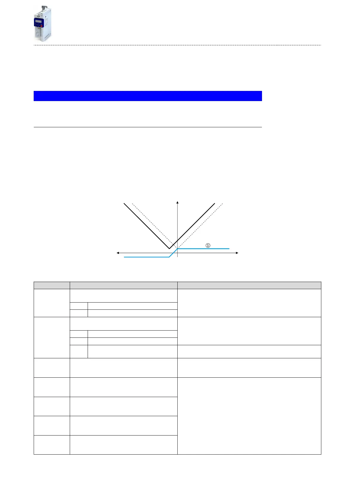
At a constant eld frequency, the output voltage of the inverter can be changed within a wide
range.
Example: Adaptaon of the voltage characterisc in case of V/f characterisc control as a
funcon of the load:
•
Clockwise rotaon (CW) is operaon in motor mode: Boost voltage.
•
Counter-clockwise rotaon (CCW) is operaon in generator mode: Lower voltage.
f
V
out
V/f characteristic
Operation in
generator mode
Operation in
motor mode
①
Selecng an addive voltage setpoint
A detailed conguraon example for this funcon can be found in the following subchapter.
Parameter Name / value range / [default seng] Info
0x2B13:001 Addive voltage impression: Enable Funcon
•
From version 02.00
1 = enable funcon.
0 Disable
1 Enable
0x2B13:002 Addive voltage impression: Setpoint source
•
From version 02.00
Selecon of the source for specifying the addive voltage setpoint.
•
100 % ≡ Rated voltage 0x2C01:007 (P320.07)
1 Analog input 1
2 Analog input 2
3 Network The addive voltage setpoint is dened via the mappable NetWordIN5
0x4008:005 (P550.05)data word.
0x2B13:003 Addive voltage impression: Actual voltage
•
Read only: x V
•
From version 02.00
Display of the current (boosted or lowered) voltage.
0x2636:004
(P430.04)
Analog input 1: Min PID value
(Analog input 1: AI1 PID @ min)
-300.00 ... [0.00] ... 300.00 PID unit
Denion of the seng range for PID control.
•
The standard setpoint source for the reference value of PID control is
selected in 0x2860:002 (P201.02).
0x2636:005
(P430.05)
Analog input 1: Max PID value
(Analog input 1: AI1 PID @ max)
-300.00 ... [100.00] ... 300.00 PID unit
0x2637:004
(P431.04)
Analog input 2: Min PID value
(Analog input 2: AI2 PID @ min)
-300.00 ... [0.00] ... 300.00 PID unit
0x2637:005
(P431.05)
Analog input 2: Max PID value
(Analog input 2: AI2 PID @ max)
-300.00 ... [100.00] ... 300.00 PID unit
Addional funcons
Addive voltage impression
323

 Loading...


