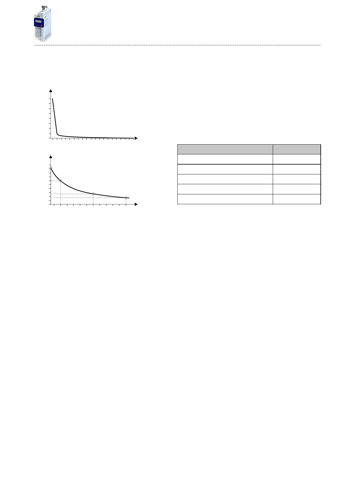
The following two diagrams show the relaon between the motor load and release me of
the monitoring under the following condions:
•
Maximum ulisaon 0x2D4B:001 (P308.01) = 150 %
•
Speed compensaon 0x2D4B:002 (P308.02) = "O [1]" or output frequency ≥ 40 Hz
2000
4000
6000
8000
10000
14000
16000
12000
[s]
0
[%]
112
113
114
115
116
117
118
119
120
121
122
123
124
125
126
127
128
129
130
0
10
20
30
40
50
60
70
80
90
100
[s]
[%]
140
160
170
180
190
200
210
220
230
240
250
150
111
Load
Load
Release time
Release time
Depending on the seng in 0x2D4B:001 (P308.01), the release me from the diagrams can be
derived as follows:
•
Calculaon of the load rao:
Load rao = 150 % / maximum ulisaon 0x2D4B:001 (P308.01)
(example: 0x2D4B:001 (P308.01) = 75 % à load rao = 150 % / 75 % = 2)
•
Calculaon of the release me of the monitoring:
Release me = actual load * load rao
(example: actual load = 75 % à release me = 75 % * 2 = 150 %)
•
Looking up the release me from the above table based on load * load rao.
(example: Load * load rao = 150 % à release me = 60 s)
Motor control
Motor protecon
Motor overload monitoring (i²*t)
163

 Loading...


