General mode of operaon
The following diagram demonstrates the general funconing in automac operaon:
t
t
t
t
0 Hz
30 Hz
10 Hz
20 Hz
40 Hz
50 Hz
60 Hz
-40 Hz
-60 Hz
-50 Hz
-30 Hz
-20 Hz
-10 Hz
t
0 Hz
30 Hz
10 Hz
20 Hz
40 Hz
50 Hz
60 Hz
t
t
t
t
0x2820:015
0x2820:002
0x2820:003
0x2820:013 0x2820:013
0x2DDD
0x2820:008
Holding load
Power section switched-on
Digital input 3 [13] Reversal rotation direction
Output frequency
Active [0]Brake released [1]
Brake status
Release holding brake [115]
Output signals
Output trigger
Digital input 1 [11] Run
Constant TRUE [1] Enable inverter
Input signals
Frequency setpoint selection
FunctionTrigger
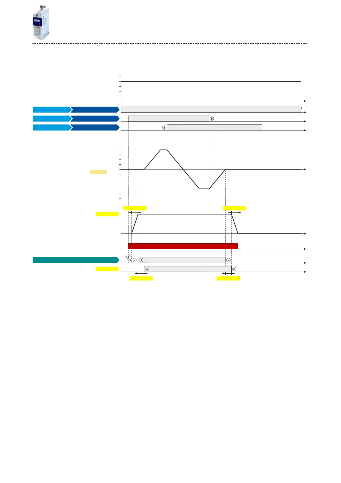
①
If the inverter is enabled and no error is acve, the motor can be started with the "Run" funcon in forward rotang direcon.
The power secon is switched on and the motor is magnesed rst.
②
The brake holding load set in 0x2820:008 (P712.08) is build up via the ramp set in 0x2820:013 (P712.13).
③
The holding brake is released. For this purpose, the output trigger "Release holding brake [115]" is set to TRUE. This trigger must be
assigned to a digital output or, in the simplest case, to the relay which then switches the brake supply.
④
Aer the release me 0x2820:003 (P712.03) has elapsed, the motor is accelerated to the setpoint.
The brake status "Brake released [1]" is displayed in 0x2820:015 (P712.15).
⑤
In case the direcon of rotaon reverses, the holding brake remains released.
⑥
If "Run" is set to FALSE, the motor is stopped with the stop method set in 0x2838:003 (P203.03). In the example: Stop with standard ramp.
⑦
Then the holding brake is closed again.
⑧
Aer the closing me 0x2820:002 (P712.02) has elapsed, the brake status "Acve [0]" is displayed in 0x2820:015 (P712.15).
The brake holding load is reduced again via the ramp.
Addional funcons
Holding brake control
Brake holding load
305

 Loading...


