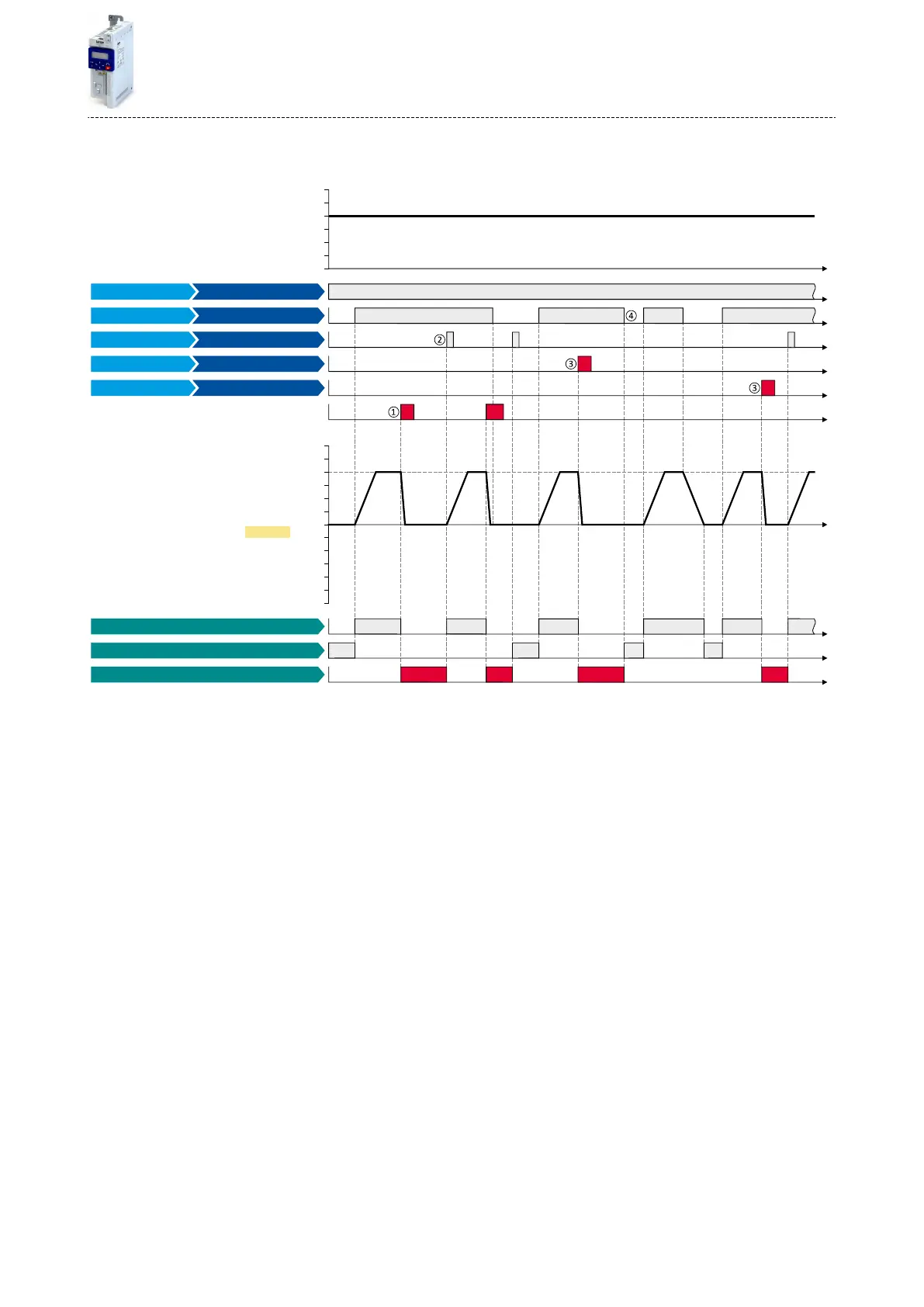
The following signal ow illustrates the reset of an error both with the "Reset error" funcon
②
and by cancelling the start command
④
:
t
t
0 Hz
30 Hz
10 Hz
20 Hz
40 Hz
50 Hz
60 Hz
0 Hz
30 Hz
10 Hz
20 Hz
40 Hz
50 Hz
60 Hz
-40 Hz
-60 Hz
-50 Hz
-30 Hz
-20 Hz
-10 Hz
t
t
t
t
t
t
t
t
t
0x2DDD
Running [50]
Stop active [53]
Activate fault 2
Activate fault 1
Run
Digital input 4 [14]
Digital input 3 [13]
Digital input 1 [11]
Constant TRUE [1]
Digital input 2 [12]
Error condition
Error active [56]
Output signals
Status signals
Output frequency
Reset error
Enable inverter
Input signals
Frequency setpoint selection
FunctionTrigger
The status signals can be assigned to digital outputs. 4Conguraon of digital outputs ^ 415
①
If an error condion is acve in the inverter, the motor is brought to a standsll with the quick stop ramp. The inverter is then disabled.
Excepon: In case of a serious error, the inverter is disabled immediately. The motor becomes torqueless (coasts).
②
If the error can be reset, the error state can be le again with the "Reset fault" funcon (if the error condion no longer exists). The motor
accelerates again to the setpoint since the start command is sll acve.
③
The funcons "Acvate fault 1" and "Acvate fault 2" serve to set the inverter from the process to the error status.
④
If the error can be reset, the cancelled start command results in leaving the error state (if the error condion no longer exists).
Related topics
4Error handling ^ 90
Flexible I/O conguraon
Reset error
385

 Loading...


