t
t
0 Hz
30 Hz
10 Hz
20 Hz
40 Hz
50 Hz
60 Hz
0 Hz
30 Hz
10 Hz
20 Hz
40 Hz
50 Hz
60 Hz
-40 Hz
-60 Hz
-50 Hz
-30 Hz
-20 Hz
-10 Hz
t
t
t
t
t
t
!
Relais
0x2DDD
Output trigger
Holding brake
active
Holding brake
active
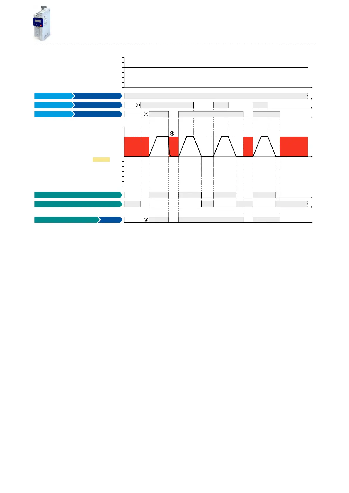
Running [50]
Stop active [53]
Run
Digital input 2 [12]
Constant TRUE [1]
Digital input 1 [11]
Release holding brake [115]
Output signals
Status signals
Output frequency
Release holding brake
Enable inverter
Input signals
Frequency setpoint selection
FunctionTrigger
The status signals can be assigned to digital outputs. 4Conguraon of digital outputs ^ 415
①
As the holding brake is acve, the motor does not yet start to rotate aer the start command.
②
The holding brake is released. The motor is led to the setpoint.
③
In this example, the "Release holding brake [115]" trigger is assigned to the relay that switches the brake supply. In idle state, the holding
brake is applied. If the relay is energised, the holding brake is released.
④
Note: Holding brakes are not intended for braking during operaon. The increased wear caused by braking during operaon may destroy
the holding brakes prematurely!
Flexible I/O conguraon
Releasing holding brake manually
389

 Loading...


