Mechanical installation
Standard devices in t he power range 3 ... 22 kW
Assembly in push-through technique (thermal separation)
5
121
EDS84ASC552 EN 10.0
5.3.2 Assembly in push-through technique (thermal separation)
The E 84AVxxD... controllers are designed for mounting in push-through design. The scope
of supply includes all parts required for mounting.
Installation steps
How to proceed:
1. Prepare mounting cutout and mounting holes (threaded holes M5 recommended).
2. Insert the 8400 frequency inverter into the mounting cutout.
3. Tighten with 6 screw and washer assemblies M5 x 10 (cross screw connection
recommended).
4. SealthescrewstoensuretheIP54enclosureorULtype12.
StateLine, HighLine
8400GG106e
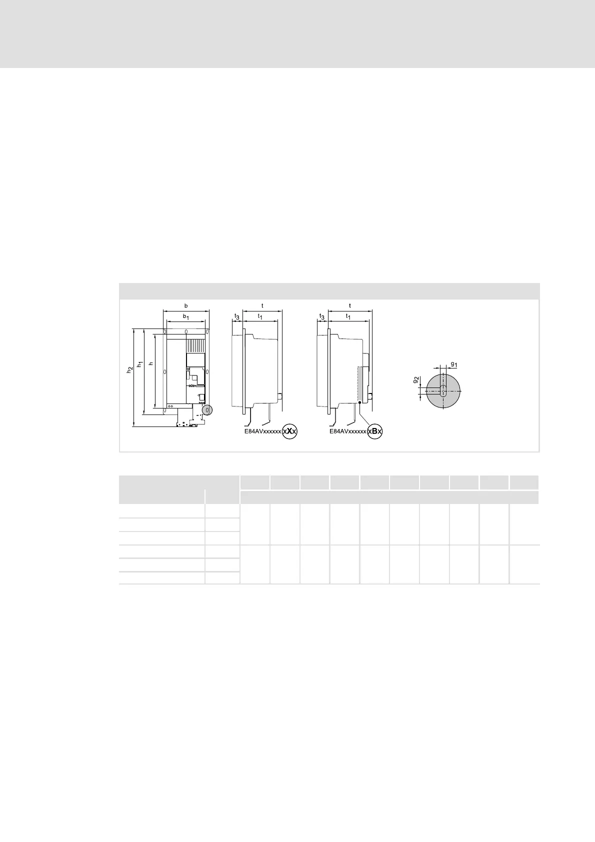
Fig. 5-25 Device dimensions
h b t h
1
h
2
b
1
t
1
t
3
g
1
g
2
[kW] [mm]
E84AVxxD3024xXx3
270 174 141 318 366 140 128 64 6 5
E84AVxxD4024xXx 4
E84AVxxD5524xXx 5.5
E84AVxxD3024xBx 3
270 174 161 318 366 140 148 64 6 5
E84AVxxD4024xBx 4
E84AVxxD5524xBx 5.5