Electrical installation
StateLine C control terminals
Digital inputs and outputs
6
229
EDS84ASC552 EN 10.0
Example circuit
E84AVSC...
24 V
int.
24E
DI1
DI2
DI3
DI4
RFR
DC 24 V
(+19.2 … +28.8 V)
S1
3.3k
3.3k
3.3k
3.3k
3.3k
X4
GND-IO
DO1GIO 24I
GND-IO
E84AVSC...
24 V
int.
24E
DI1
DI2
DI3
DI4
RFR
S1
3.3k
3.3k
3.3k
3.3k
3.3k
X4
GND-IO
DO1GIO 24I
GND-IO
8400SLC015 8400SLC016
DC 24 V
(+19.2 … +28.8 V)
E84AVSC...
24 V
int.
24E
DI1
DI2
DI3
DI4
RFR
S1
3.3k
3.3k
3.3k
3.3k
3.3k
X4
GND-IO
DO1GIO 24I
GND-IO
DC 24 V
(+19.2 … +28.8 V)
S1
"
E84AVSC...
24 V
int.
24E
DI1
DI2
DI3
DI4
RFR
3.3k
3.3k
3.3k
3.3k
3.3k
X4
GND-IO
DO1GIO 24I
GND-IO
8400SLC017 8400xLC022
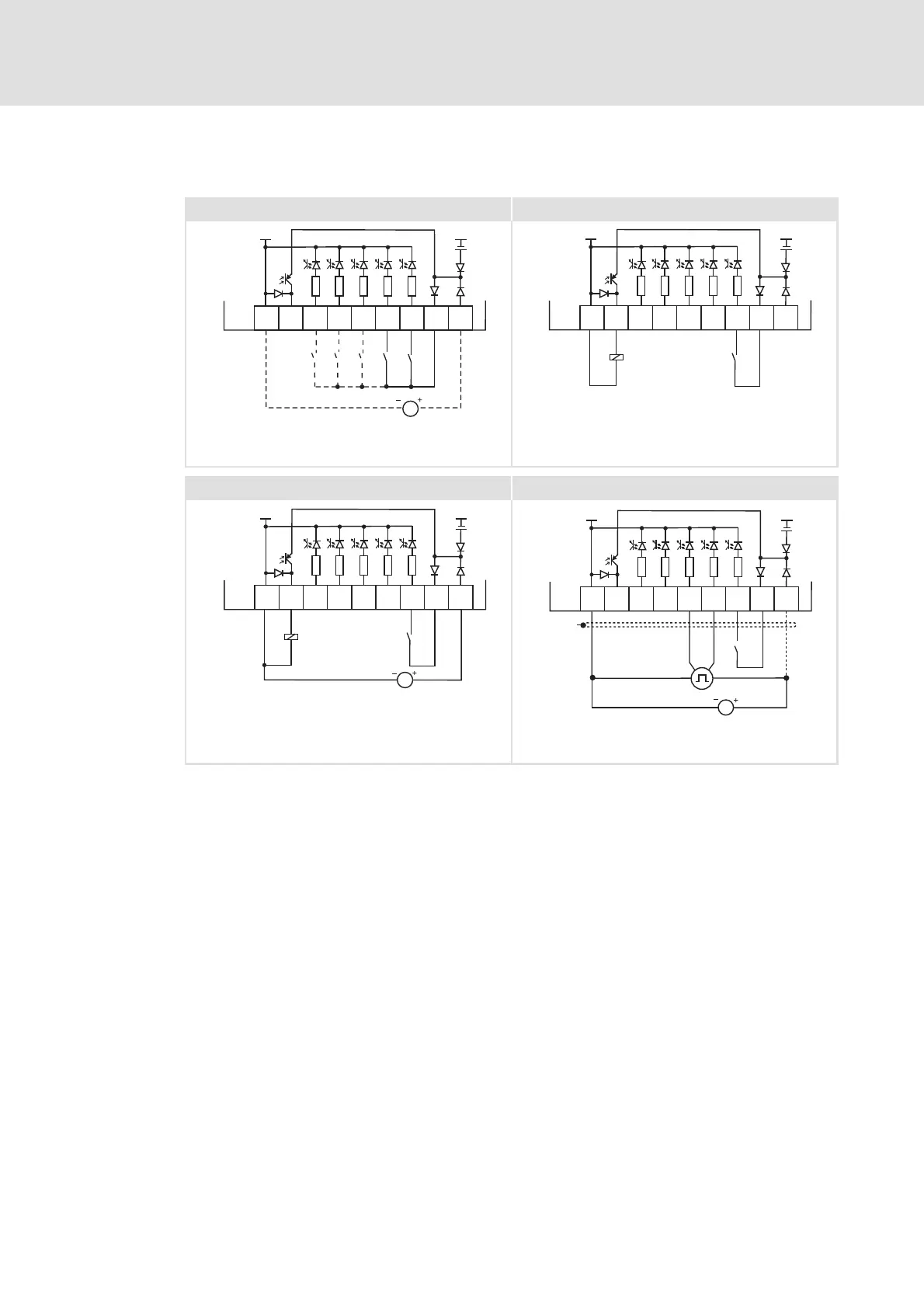
Fig. 6 -37 Wiring examples of the digital inputs and outputs
Wiring with one (or several) digital input (here: DI1), e.g. a PLC; optional: external
24 V supply
Digital control (relay, valve, ...) with internal 24 V supply
Digital control (relay, valve, ...) with external 24 V supply
Connection of an HTL incremental encoder with a maximum input frequency of
10 kHz
DI1 track A
DI2 track B
RFR Input for controller enable; wiring is always required.
GIO GND-IO Ground reference potential for the digital inputs and outputs
X4 Terminal for the digital inputs and outputs