Electrical installation
HighLine C control terminals
Analog inputs and o utputs
6
233
EDS84ASC552 EN 10.0
Example circuit
"
GND-A
X3
A2IO2I
E84AVHC...
A2U
O2U A1IO1I
A1U
O1U
AR
GA
+10 V /
10 mA
"
U
GND-A
X3
A2IO2I
E84AVHC...
A2U
O2U A1IO1I
A1U
O1U
AR
GA
+10 V /
10 mA
8400HLC012 8400HLC012
"
B
GND-A
X3
A2IO2I
E84AVHC...
A2U
O2U A1IO1I
A1U
O1U
AR
GA
+10 V /
10 mA
"
-
+
GND-A
X3
A2IO2I
E84AVHC...
A2U
O2U A1IO1I
A1U
O1U
AR
GA
+10 V /
10 mA
8400HLC012 8400HLC012
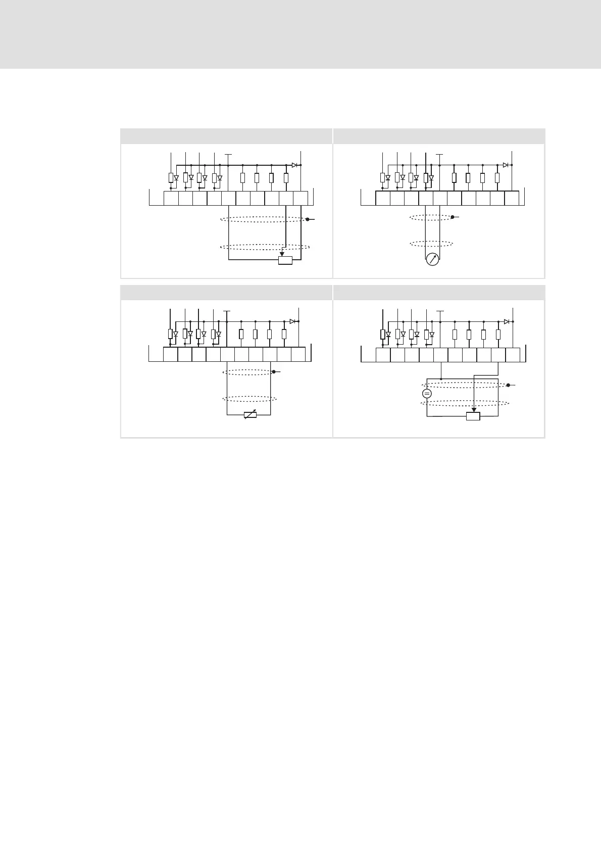
Fig. 6-41 Wiring examples of the analog inputs and outputs
Potentiometer with internal controller supply
Terminal assignment of the analog output signal, e.g. by a measuring instrument
External master current selection based on a sensor signal 0-20 mA.
Potentiometer with external supply
X3 Terminal for the analog inputs and outputs
GA GND-A Ground reference potential for the analog inputs and outputs
EMC shield connection
UMeasuringdevice