Electrical installation
HighLine C control terminals
Digital inputs and outputs
6
237
EDS84ASC552 EN 10.0
Example circuit
Note!
For s table digital output states, in particular during the starting phase of the
controller, you must use an external 24V supply for the digital outputs.
Note!
Digital inputs and digital outputs have separated reference potentials (GI and
GO). If you interconnect inputs and outputs, the reference potentials are
connected as well by an external bridge.
DC 24 V
(+19.2...+28.8 V)
S1
24 V int.
50 mA
24EDI1DI2
DI3
DI4
RFR
2.7k
2.7k
3.3k
3.3k
3.3k
X5
GND-I
DI5
DI6
DI7
GI
24I
1.6k
1.6k
3.3k
E84AVHC...
24O
DC 24 V
(+19.2...+28.8 V)
X4
DO1DO2
DO3
GO
GND-O
E84AVHC...
8400HLC045 8400HLC045
24 V int.
50 mA
24E
DI1
DI2
DI3
DI4
RFR
DC 24 V
(+19.2...+28.8 V)
S1
3.3k
2.7k
2.7k
3.3k
X5
GND-I
DI5
DI6
DI7
GI 24I
3.3k
1.6k
1.6k
3.3k
"
E84AVHC...
8400xLC022
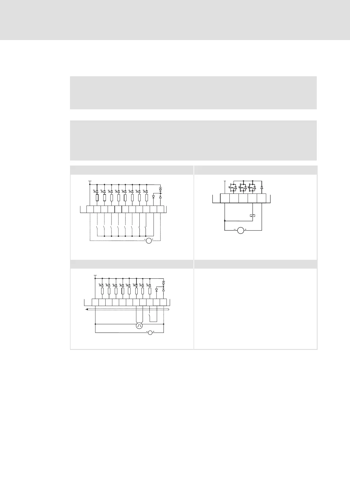
Fig. 6 -44 Wiring examples of the digital inputs and outputs
Wiring with one (or several) digital input (here: DI1), e.g. a PLC; optional: external
24 V supply
Digital control (relay, valve, ...) with external 24 V supply
Connection of an HTL incremental encoder with a maximum input frequency of
200 kHz
DI1 track A
DI2 track B
X4 Terminal for the digital outputs
X5 Terminal for t he digital inputs
GI GND-I Ground reference potential for the digital inputs
GO GND-O Ground reference potential for the digital outputs