Product description
Overview of control terminals
3
24
EDS84ASC552 EN 10.0
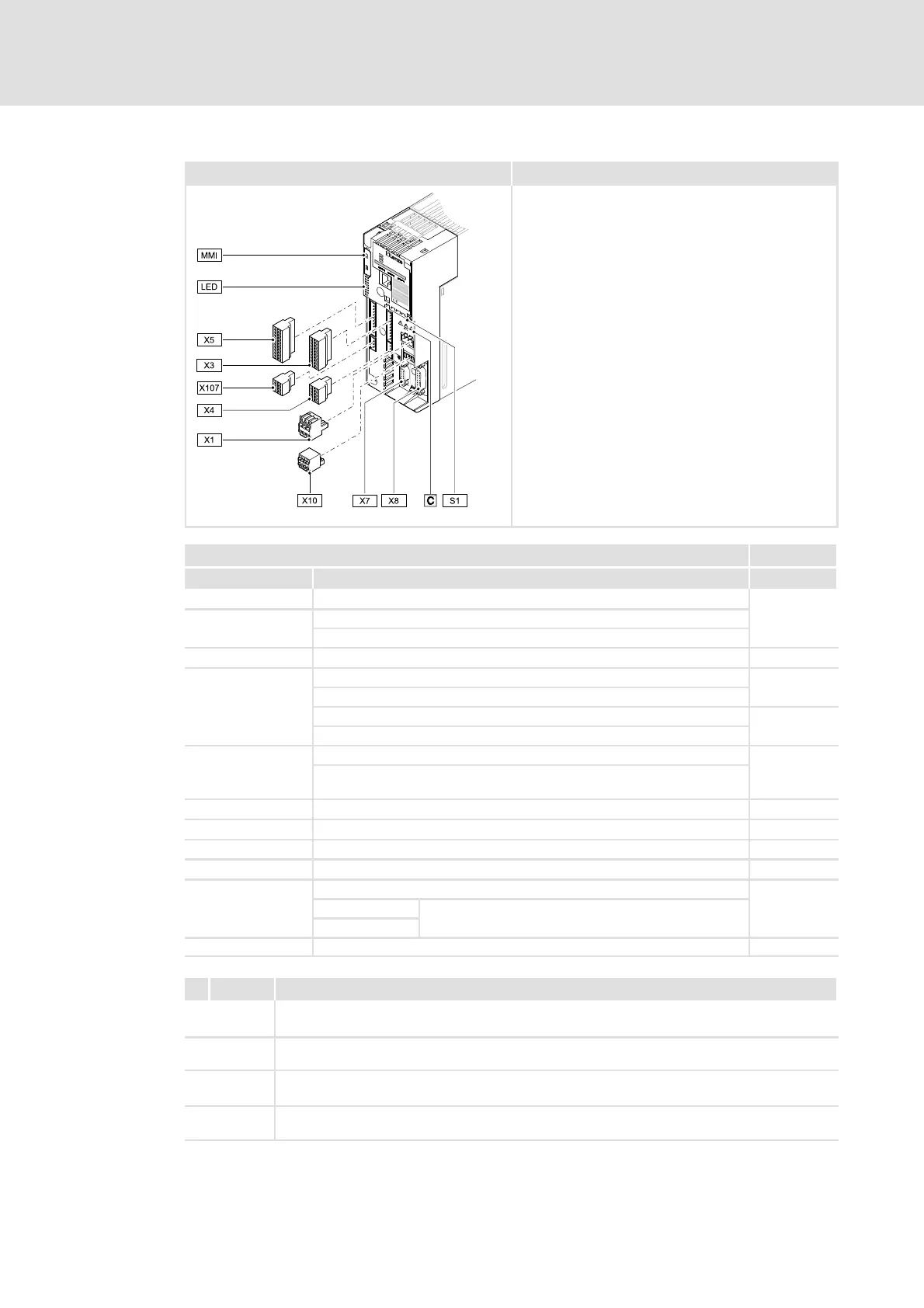
Control terminals for devices in the TopLine version
8400TLC032b
Connection Information
Pos. Description TopLine C
X1 CANopen connection
215
S1
CANopen settings
Settings for CANopen terminating resistor and axis bus
X3 Analog inputs / outputs; 10 V reference voltage 232
X4
Digital inputs; controller enable
-
24 V supply of the control electronics
Digital outputs
236
236
24 V voltage ou tput
X5
Digital inputs; controller enable
235
External 24 V supply of the control electronics; internal 24 V supply, fused
via PTC
X6 (DIAG) Diagnostic interface 223
X7 Resolver 239
X8 Encoder 240
X10 Axis bus 241
X107
24 V brake supply
238
+BD1
Connection for DC brake coil
-BD2
MMI Slot for memory module (Memory Module Interface) 295
Icon Description
Long discharge time: All power terminals remain live for a few minutes after mains
disconnection! The duration is given under the warning symbol on the device.
High leakage current: Carry out fixed installation and PE connection according to EN 61800-5-1!
Electrostatic sensitive devices:Beforeworkingonthedevice,thepersonnelmustbefreeof
electrostatic charge!
Hot surface: Risk of burns! Hot surfaces should not be touched without wearing protective
gloves.