Safety engineering
Technical data
10
282
EDS84ASC552 EN 10.0
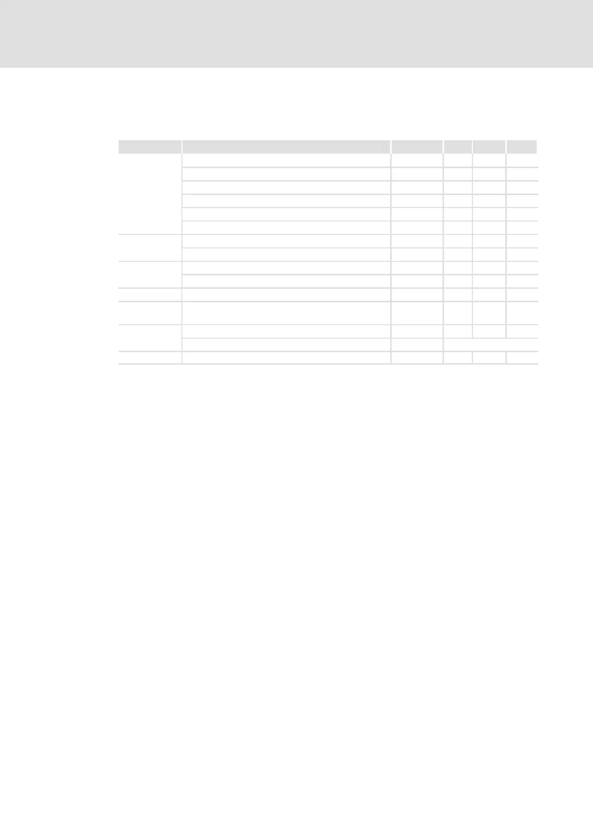
HW revision: Up to 1B - detailed features of the inputs and outputs of the safety
system
Terminal Specification [Unit] Min. Typ. Max.
SIA, SIB
Low signal
V -3 0 5
High signal V 15 24 30
Input capacitance at switch-off nF 4
Input delay (tolerated test pulse) ms 1
Switch-off time (depending on the controller) ms 2.5 4
Running time ms 3
SIA
Input current mA 100 170
Input capacitance at switch-on, reduced F 20
SIB
Input current mA 28 35
Input capacitance at switch-on, reduced F 5
GI Ground for SIA/SIB
24O, GO Supply voltage U
24O
for the output DO1 by a safely
separated power supply unit (SELV/PELV)
V 18 24 30
DO1
Low signal V 0.8
High signal V U
24O
-1V
24O, GO, DO1 Output current A 0.7
The function of the safety unit meets the requirements of the following standards:
ƒ Category 4 and PL e according to EN ISO 13849-1
– To comply with category 4, the external wiring and the cable monitoring must
meet the requirements of category 4.
– Ensure that short circuits cannot occur in the external wiring.
ƒ SIL 3 according to IEC 61508
– The safety unit does not contribute to the probability of failure on demand (PFD)
and probability of failure per hour (PFH) of IEC 61508.