An Ex conform solution is needed for the motor cable to leave the Ex area (see Figure 5). One option is an
Ex certified cable sealing system as listed in Table 4 (see Pos. 10) and shown in Figure 2.
A protective earth wire (minimum Wire Gauge AWG14, copper diameter 1.63mm, cross section 2.08mm
2
)
shall be attached to the Ex specific motors by following the instructions outlined below.
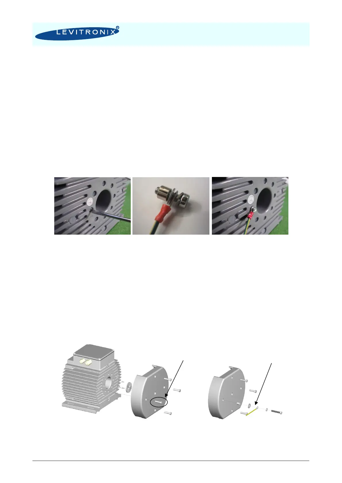
1) Motors used without cooling module ACM-4.3
A protective earth wire shall be attached to the Ex specific motor housing by using one of the eight M4
threads on the backside of the motor.
▪ Remove one of the eight M4 screws on the backside of the motor
▪ Use a crimp cable lug to connect the earth wire
▪ Attach the crimp cable lug with a M4 x 10 mm stainless steel screw, a washer disc, a spring lock
washer and spacer sleeve (6 mm long) to the motor according to (Figure 32)
Figure 32: Attachment of a protective earth wire to the backside of the motor
2) Motors used with cooling module ACM-4.3
A protective earth wire shall be attached to the Ex specific motor housing by using one of the four M6
threads on the backside of the motor.
▪ Mount the cooling module ACM-4.3 to the motor according to (Figure 12)
▪ Remove one of the four M6 screws on the mounted cooling module
▪ Use a crimp cable lug to connect the earth wire
▪ Attach the crimp cable lug with a M6 x 40 mm stainless steel screw, a washer disc and a spring lock
washer to the motor through the cooling module (Figure 33)
Figure 33: Attachment of a protective earth wire to the backside of the motor through ACM-4.3