(L) (N) (L1) (L2) (N1)
76
ACCESSORIES INSTALLATION
How to Wire Mixing Kit
Follow below procedures Step 1 ~ Step 3.
Step 1. Uncover front cover of the unit.
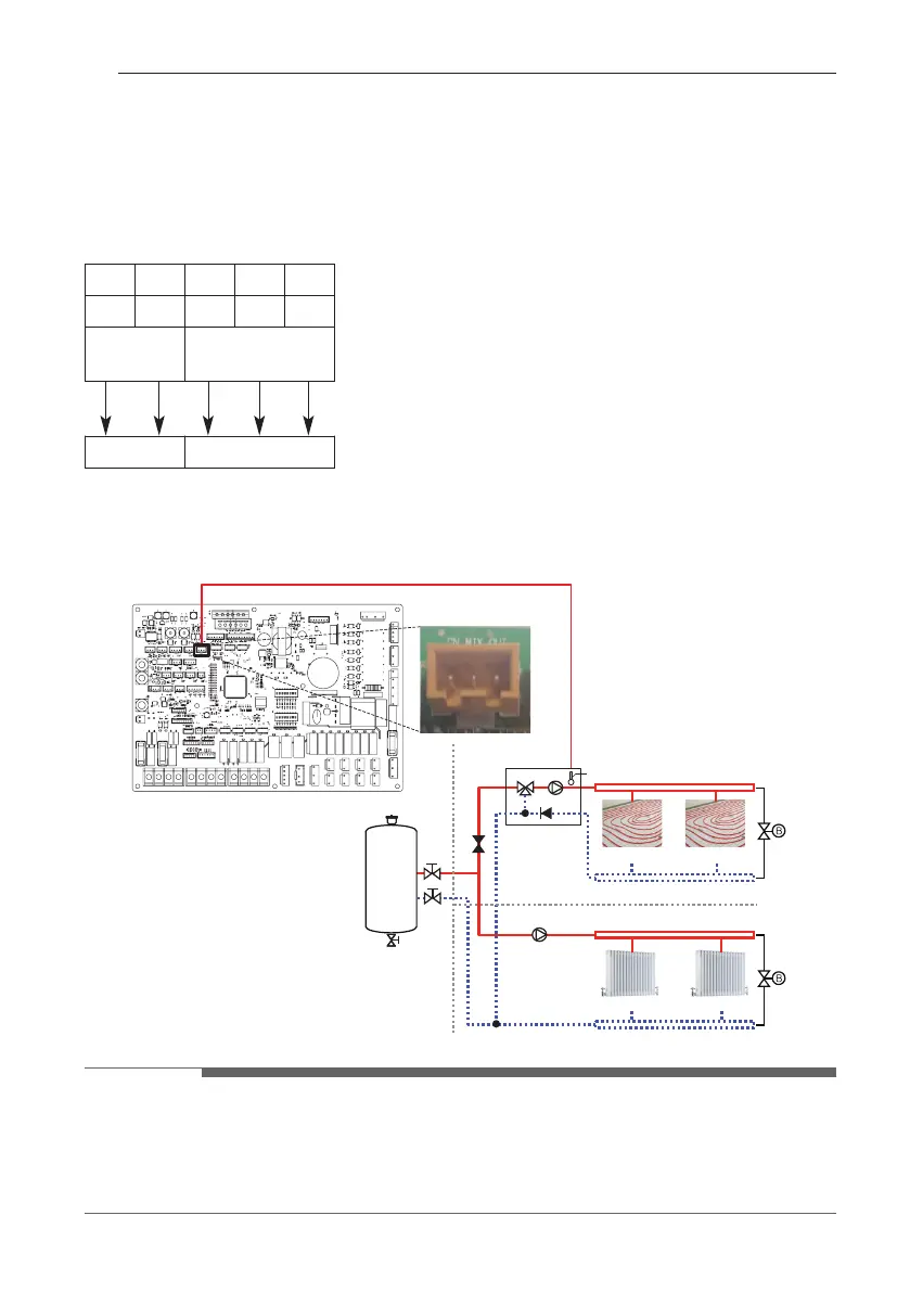
Step 2. Find terminal block and connect wire as below
Step3. Insert the temperature sensor to 'CN_MIX_OUT' (Brown) of the main PCB as shown
below. The sensor should be mounted correctly to discharge pipe of mix pump as shown
below.
CN_MIX_OUT
Indoor PCB
Floor heating loop
Mix
Mixing circuit temp. sensor
Mix Kit
[Circuit 1] Direct Circuit
[Circuit 2] Mixing Circuit
Floor heating loop
Radiator Radiator
Buffer
Tank
NOTE
• The location of the external pump may vary depending on the installer settings.
• Temperature sensor specification:
LG-accessory PRSTAT5K10 at 25 °C : 5 kΩ
Minimum operating temperature range : -30 °C~100 °C
TB 1
(L) : Live signal from PCB to mix pump
(N) : Neutral signal from PCB to mix pump
(L1) : Live signal (for Normal* Closed type) from PCB to
mixing valve
(L2) : Live signal (for Normal Open type) from PCB to
mixing valve
(N1) : Neutral signal from PCB to mixing valve
*Closed = NOT Mixed
MIX PUMP MIXING VALVE
7 8 9 10 11
L N L1 L2 N
MIX PUMP MIXING VALVE
 Loading...