4 | Description LINXON
20 / 90 LX218-Operating-Manual-en1-04-(1908)
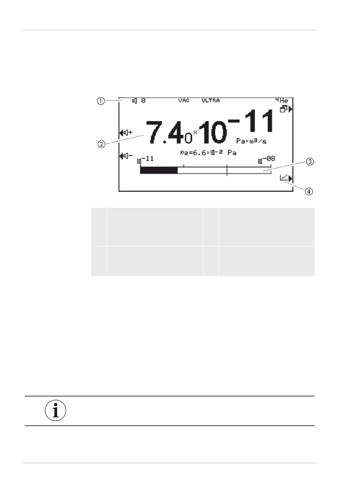
4.3.2.6 Measuring screen layout
The measured leak rates are displayed numerically with a bar graph or graphically in a
diagram as a function of the measuring time. Use the bottom right button to switch
between the display options. Next to this button is the symbol for the analog display or
the graphical display.
Fig.5:
Numerical display, measuring screen
1 Information area
(volume, operation mode,
measuring situation, ZERO active,
tracer gas)
2 Currently measured value
(displayed using pressure at inlet
flange p2)
3 Bar graph
(the currently measured value is
displayed as a bar graph)
4 Switch to measuring screen
4.3.3 Vacuum connections
4.3.3.1 Inlet
The inlet is located on the upper part of the device. This is a DN 25 KF flange.
If you select the vacuum leak test mode, connect the test object or the vacuum
chamber to the flange.
If you are testing applications with dust or dirt, use the O-ring with filter, see
"Shipment, Transport, Storage [}12]”. In this case, the pump down times are
extended.
Also use this inlet for the connection of the sniffer line or the test chamber.