LINXON Description | 4
LX218-Operating-Manual-en1-04-(1908) 23 / 90
5 Shielding 6 +24 V (0.8 A slow-blowing fuse)
INPUT/OUTPUT
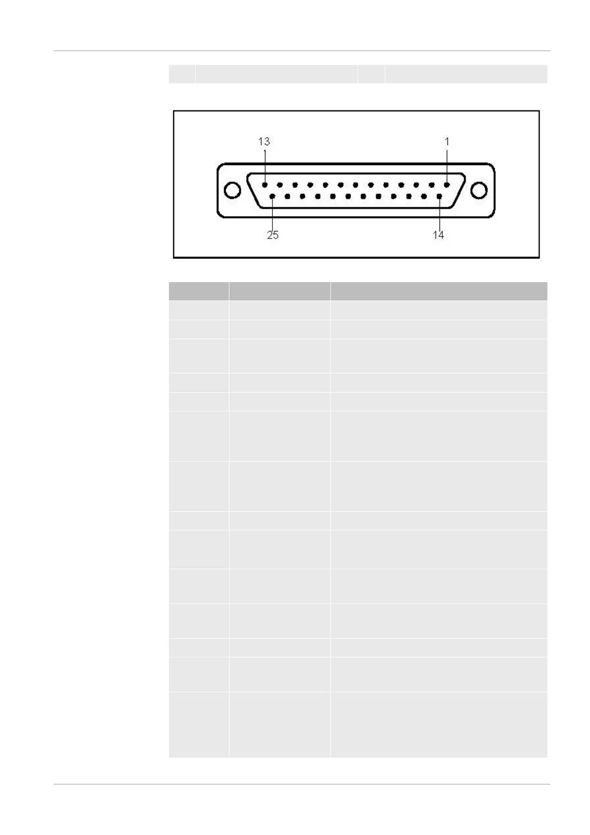
Input and output signals, 25-pin, D-Sub, sockets.
Fig.8:
D-Sub connector
Pin Signal Explanation
1 Channel 1 Analog output, 0 … 10 V, Ri 3 Ω.
2 Channel 2 Analog output, 0 … 10 V, Ri 3 Ω.
3 AGND Reference potential of analog outputs, galv.
isolated
4 Audio output (headphones or active box)
5 Reference potential for the audio output
6 … 13 DI 1 … 8 Digital inputs, +18 … 30 V (approx. 5 mA). The
functions are triggered with the positive edge.
Equal to the control unit.
6 Start/Stop Starts the measurement in the "Ready" state
and stops the measurement in the "Measuring"
state.
7 Vent Venting in the "Manual venting" setting.
8 ZERO Function of the ZERO button.
If pressed longer than 3 s, ZERO is canceled.
9 Calibrate Starts the calibration or for the confirmation of
"Calibration Acknowledge" (Pin 19)
10 PARA 2 When activating: "Parameter set 2 is loaded."
When deactivating: "Parameter set 1 is loaded."
11 Bypass Response: "Bypass option available"
14 DGND Reference potential for the digital inputs,
galvanically isolated
15 … 22 DO 1 … 8 Digital outputs, not galvanically isolated, active
24 V ± 10%, passive at DGND (0 V) Maximum
permissible current: 800 mA for all outputs
together